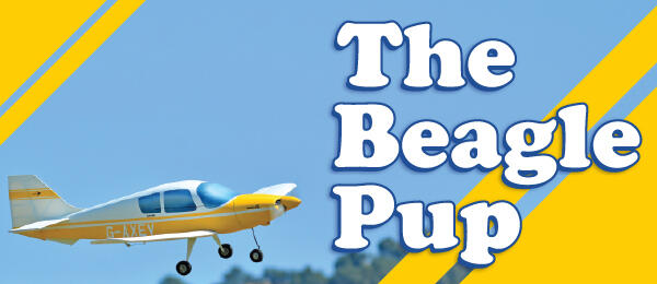
Off-the-beaten-path subject makes for a simple stick-and-tissue model!
From time to time, I search the internet for new subjects to model. When I’m in that mode, I have a general idea of what I want, and the goal is to find something off the beaten track.
My most recent foray was in search of a general aviation aircraft that could be turned into a very lightweight model to keep in the trunk for flying from the parking lot at work. Specifically, I needed something that was single engine and low wing with minimum detailing required. What I found was the Beagle Pup.
PURCHASE FULL PLANS HERE
OR DOWNLOAD FREE PLANS!
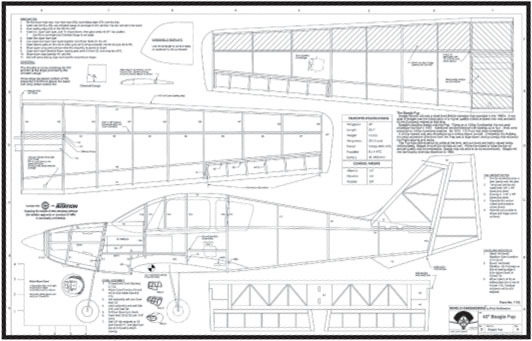
Full Plans
Tiled Plans
The creator of the Pup was British Executive & General Aviation Limited, with the loose acronym of BEAGLE (Beagle) for short. Headed by the U.K. heavy-hitter aviation firms Bristol and Miles, Beagle Aircraft set out to build a higher-quality civilian airplane than what was available on the European market at that time.
The resulting prototype, a two-seater aircraft flying on a 100-hp Continental engine, made its first flight in 1967. Additional models followed with seating for up to four. Most of these were powered by 150-hp Lycoming engines. By 1970, 175 Pups had been completed.
A 200-hp variant was also developed as a military liaison aircraft. Christened as the Bulldog, the most prominent difference from the Pup was a large blown sliding canopy that replaced the Pup’s glazing and doors.
The Pup was well received by pilots at the time, and survivors are highly valued today. Unfortunately, Beagle Aircraft did not fare as well. While the desire to raise the bar on aircraft quality was commendable, Beagle was not able to do so economically and fell into bankruptcy, dissolving in 1969.
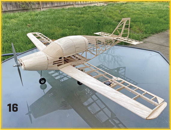
As for this model, the design relies on classic stick-and-tissue-type construction. A laser-cut kit is available, but the number of intricately shaped parts has been kept low to reduce kit cost and to make hand-cutting manageable.
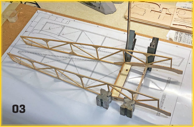
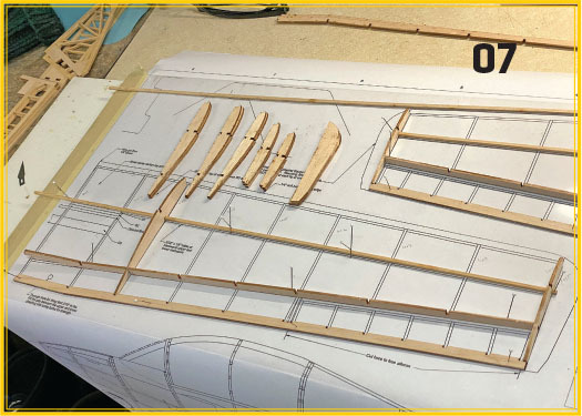
Tail Group Assembly
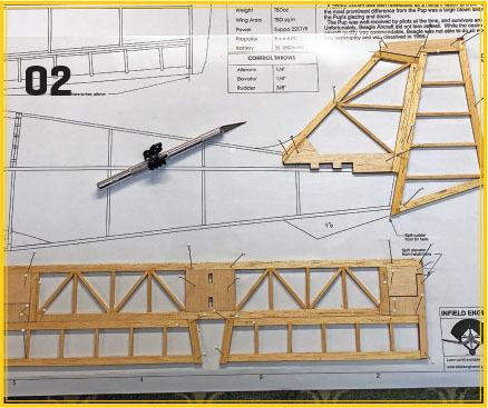
Start the tail group by cutting balsa strips of 1/8 × 1/4 inch for the outlines and 1/16 × 1/8 inch for the bracing. Pin the kit parts down to the plans. Cut, fit, and glue the outline and bracing parts between the kit parts, as shown.
Once they have cured, unpin the tail group parts and separate the rudder and the elevators. Sand the leading edges (LEs) and trailing edges (TEs) of the tail group parts as shown on the plans. I used narrow strips of CA hinge material on the prototype to hang the control surfaces.
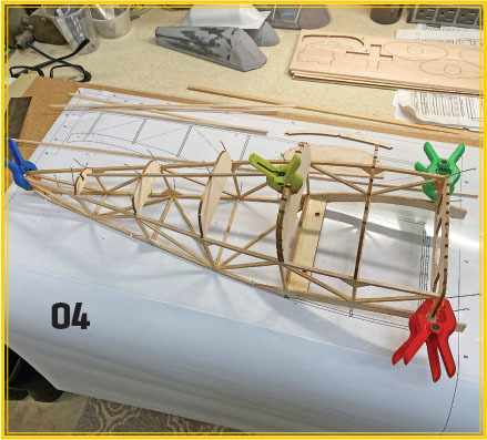
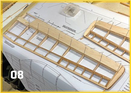
Building the Fuselage
Begin the fuselage construction by preassembling some of the components. These include the wing boss, formers F3A and F3B, and the wing pin doubler on former F2.
Build two identical side panels over the template on the plans. Install bracing, as shown, and allow the panels to cure fully before removing them from the board.
Join the two side panels with the wing boss and former F5. Make sure that the panels stand vertically and that the lower spar on each panel is flush with the board. Once they are cured, glue upper former F6 to the upper spars. Make sure to tip F6 back slightly as shown—this will make attachment of the cabin hatch easier.
Now that the center section is secure, pull the tail of the fuselage assembly closed by adding the upper formers and lower cross braces. Begin at former F7 and work back to F9. Install former F10 at the tail end. The wide end of F10 goes to the top—this sets the width of the opening of the fuselage into which the back of the tail fin will be inserted. Now join formers F6 through F9 together with a few stringers.
Pull the front of the fuselage assembly together by gluing formers F3A/F3B into place. Pin the hatch formers F3H through F6H into place—but don’t glue them to the fuselage. Connect them together by gluing keel K1 to each of them.
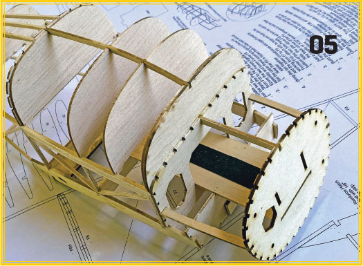
Build up the front of the fuselage by gluing F2/WP to the front of the wing saddles. Now glue battery tray BATT to formers F2, F3, and F5. Attach firewall F1 to BATT and attach keels K2 and K3 to hold it into position.
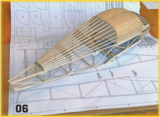
Complete the fuselage framework by adding the rest of the stringers to the turtledeck and to the front fuselage assembly between former F3 and the firewall. Plank the canopy hatch from F3H to F6H with 1/16-inch balsa while it is still attached to the fuselage assembly. Once it’s cured, remove the canopy hatch by cutting keel K1 between formers F3 and F3H and lifting the hatch off. Add locating pins and magnets to hold the hatch into position.
Framing the Wing
Start the wing halves by pinning the lower main spar, rear main spar RS, and the TE over the plans. Dry-fit a rib to each end of the wing to finetune the placement of the spars. Glue wing ribs W2 through W9 into position. Use the dihedral gauge to set the angle of ribs W2. Stand ribs W3 through W9 vertically to the board.
Glue the LE to ribs W2 through W9. Once they are cured, crack parts LE, the lower main spars, and parts TE where shown. Glue center ribs W1 into position using RS to set the height and the dihedral gauge to set the angle. Flood the cracked joints with CA to lock the assembly into position. Add the upper main spar.
Now build the ailerons. Glue aileron parts A1 through A4 in order and glue A2 to A3 as a doubler, but do not glue A2 to RS. The aileron parting line will be here. Add wingtip part WT.
Sheet the upper wing where it’s shown while the assembly is pinned to the board. Cut a panel of 1/16-inch balsa to span from rib W2 to rib W9. Dampening the upper surface of the panel will help it curve into position. Washout can be set now by shimming the TE of the wingtip with a bit of 1/8-inch scrap wood. Now glue the sheeting into place. Sheet between ribs W1 and W2 separately in the same way. Allow the sheeting to cure completely before unpinning it to ensure that the washout is set.
Sand the root faces of the wing halves then glue them together with the dihedral brace. Add 1/4-inch soft balsa to the LE and sand the assembly to shape.
The Landing Gear
Build the pockets in the wing to accept the main gear by epoxying parts G1 and G2 between the main spars and the dihedral brace. Epoxy G3 to the underside of the wing to form a pad for the rear main-gear strut to attach to.
Use the template on the plans to bend the 1/16-inch music wire struts for the landing gear. The main gear is made from three parts: left and right front struts and a single rear strut.

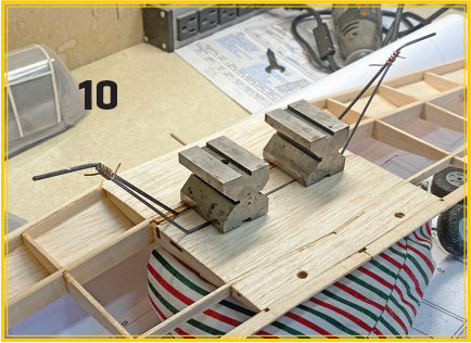
For the prototype, the main strut parts were silver-soldered together. The front struts were inserted into their pockets and their angles were finetuned. The rear strut was then clamped to G3. Light copper wire was wrapped tightly around the lower ends of the front and main struts to hold them in alignment during the soldering process.
After the main gear assembly is completed, epoxy the front main struts into their pockets. Lash the rear strut down to G3 with Kevlar line and douse this with CA. After attaching the main gear, the lower wing can be sheeted between W1 and W2.
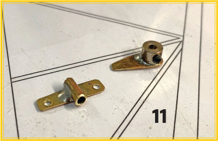
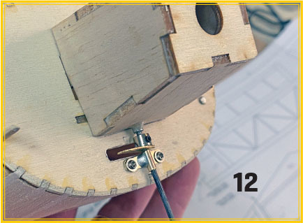
For the nose gear, the builder has options. The plans show a simple strut that can be lashed to the firewall. The Pup has a large rudder and, if it’s built lightly, it can be flown with fixed gear. With a little more work, though, a steerable nosewheel can be had.
Because the soldering torch was out already, my prototype got a scratch-built strut mount made from a bit of brass tube and flat stock. A matching tiller was made from flat brass and a nickel-plated wheel collar.
The only change that was required to the nose strut for the steering upgrade was to leave the top of the strut straight. A bit of 3/32-inch aluminum tube was epoxied between the motor mount and the firewall to serve as a bearing tube for the upper end of the strut.
The Cowling
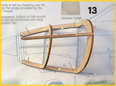
The last item left to frame is the cowling. Start by preassembling parts C1 through C3 to form the cowling opening. Assemble the left side of it over the plans. Pin keels C4 and C5 to the board. Glue formers C6 and C7 to the keels so that the formers stand vertically. Glue in keel C8 and allow it to cure before unpinning it.
Add the remaining cowling formers C6 and C7 and keel C8 to the right side of the assembly. Complete the framework by gluing the cowling opening to the front ends of the cowling keels.
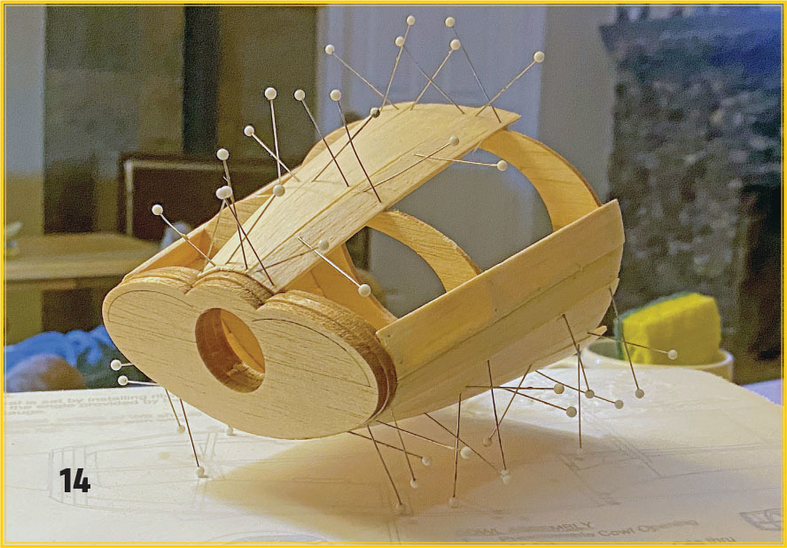
Plank the cowling with 1/16-inch balsa strips. Using softer balsa and dampening it help to make this step go quickly.
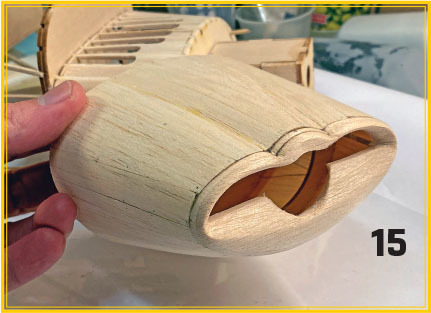
Sand the cowling to shape and use a bit of filler if it’s needed. Add a pair of locating pins and some magnets and the cowling is ready to attach to the fuselage.
Finishing
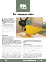
The prototype Pup was covered with Polyspan fabric using Mod Podge as an adhesive. The planked cowling and cabin were covered with light tissue. After sealing the Polyspan and tissue with four coats of very diluted water-based polyurethane, the surfaces were primed with PPG Seal Grip primer that was shot through an airbrush. All of the colors were Behr interior latex shot through the same brush.
The "Model Aviation Construction Series: Polyspan and paint" article that appeared in the October 2015 issue provides more detail on the processes that were used here. It can be found on the Model Aviation website; the link is listed in "Sources."
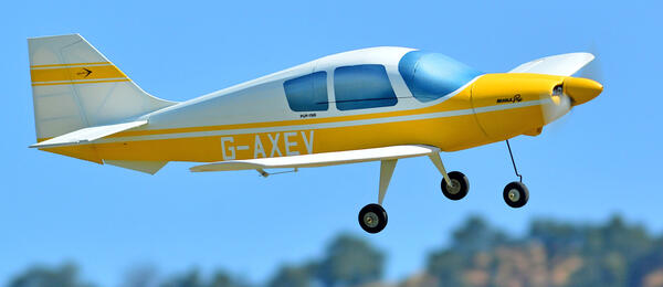
Callie Graphics supplied the graphics that were based on a file that I sent them representing aircraft G-AXEV, which is still flying in the U.K. Builders can purchase these graphics from the company or use the same file that is posted on the RCGroups build thread for the Pup.
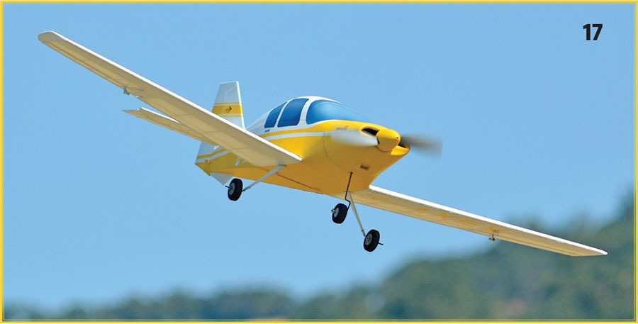
Flying
The maiden was a bit rushed by a narrow window between rainstorms, but the Pup didn’t seem to mind. I started with a quick taxi test, and the nose steering proved to be very effective. After lining up at one end of the runway, power was slowly added up to halfway and the Pup was airborne. It needed a little right trim, but otherwise, there were no surprises.
The Pup was happy to do basic aerobatics during the maiden flight, including looping and rolling. Stalls have been challenging only in the sense that it’s difficult to stall the model. Mine only weighed 15 ounces with the 950 mAh battery for the initial flight. With that low loading, the stall was extremely soft.
The large rudder is handy when it comes time to land. Again, the low loading provides predictable low-speed handling. Touchdowns have been very easy on the landing gear. One of my favorite things about this model is that it lands so softly that it has been difficult to tell when the wheels touch the runway.
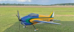
That’s a Wrap
I’ve enjoyed flying my Pup prototype so much that it took me a year to take it out of service and get the paint and markings applied. The Pup has exceeded my design goals for lightness and flying in tight quarters, and it is super cute to boot. I’m also not the fastest builder, but I managed to get this one airborne in just six weeks from when I unrolled the plans. That’s a record for me!
SOURCES:
"Model Aviation Construction Series: Polyspan and paint"
Model Aviation, October 2015


Comments
Add new comment