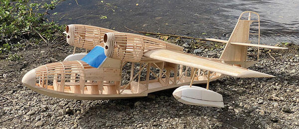
The tale that follows is the sequel to a story that began with my first design that was published by Model Aviation. Back in 2012, Executive Editor Jay Smith challenged me to design a Grumman Goose to fill a hole in the AMA Plans Service lineup. The result was a 1/12-scale Goose with a 49-inch wingspan.
The popularity of that Goose design took many of us by surprise. Jay; my friend, Tom Jacoby, of Manzano Laser Works; and I have had many conversations about why there has been so much interest in the Goose. Is it because there is an endless number of both military and colorful civilian paint schemes available? Is it the Goose’s stardom in many movies and TV shows, such as Tales of the Gold Monkey? Or is it, perhaps, just that goofy character that the Goose has?
Even after 13 years, I’m still not sure. I am certain, however, that it’s time for a new water plane with a bigger presence in the air. Rather than scale up the earlier Goose, the subject of this series of articles will be a 1/8-scale Grumman Widgeon. That will give us an even 60-inch wingspan, which is quite a bit larger than the Goose, but it can still be transported in a regular car.

This is where things get a little funny. In real life, the Widgeon is the little sister to the Goose. Playing on the popularity of the full-scale Goose that first flew in 1937, the Widgeon was released in 1941 as a smaller, more economical aircraft for private owners and regional air service. If I had it all to do over again, I’d design both models in 1/10 scale for a 59-inch wingspan Goose and a 48-inch wingspan Widgeon, but that ship has sailed.
As Grumman stuck with a winning template when deriving the Widgeon from the Goose, I will carry what works well on the Goose design over to the Widgeon. That includes the same style of lightweight balsa "stick-and-tissue"-type construction with a minimal use of plywood. This is what makes the Goose handle lightly on the water, as well as in the air.
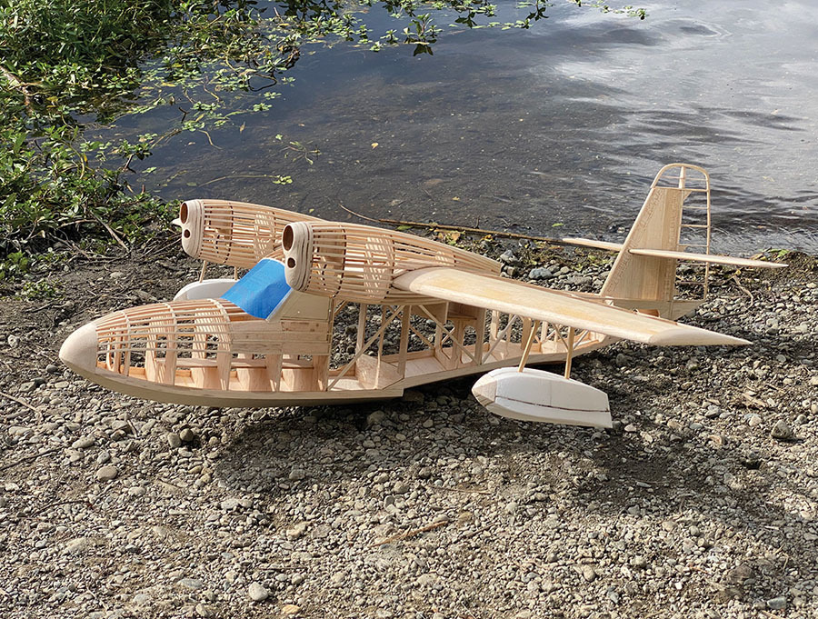
In this installment, we’ll get the basic framing of the Widgeon out of the way. The AMA version of the plans will include outlines for builders who prefer to cut by hand. The Widgeon fuselage is a bit more square than the Goose, which makes hand-cutting less challenging. Builders who are looking for an easier option can pick up a short-kit from Manzano Laser Works.
The Tail Group
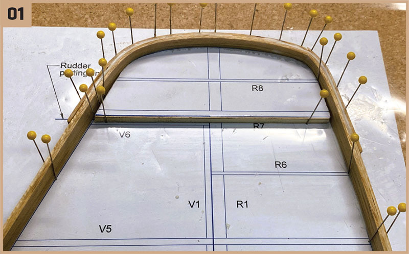
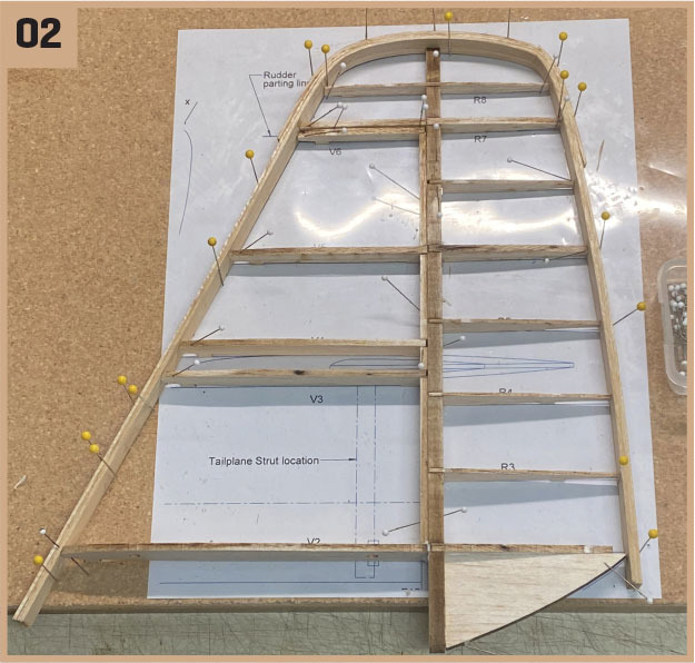
The outlines for the fin and rudder will be laminated from three strips of 1/16-inch balsa. Begin construction by preparing a form. Since only the top of the fin/rudder is curved, I made a partial form for the prototype. After soaking strips of softer balsa overnight, they were wrapped around the form and pinned into place one at a time. Titebond was used to hold the strips together. Once fully cured, the laminated outline is much tougher than just an assembly of balsa parts.
Glue the fin and rudder parts into place inside the outline in numerical order. These parts have alignment feet that go toward the building board to keep the assembly square as it goes together. Separate the rudder from the fin by cutting through the outline where shown.
Sheet the top side of the fin while it is pinned to the board to make sure that it is true. Once cured, unpin and remove the alignment feet. The underside can now be sheeted. For the prototype, I left a section of sheeting open in order to route the elevator control rod later.
The horizontal stabilizer and elevators have square tips that don’t lend themselves to lamination. Skip that step and build the horizontal stabilizer/elevators in the same way as the vertical parts.
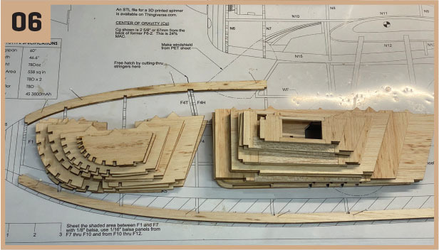
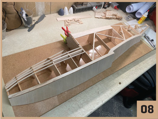
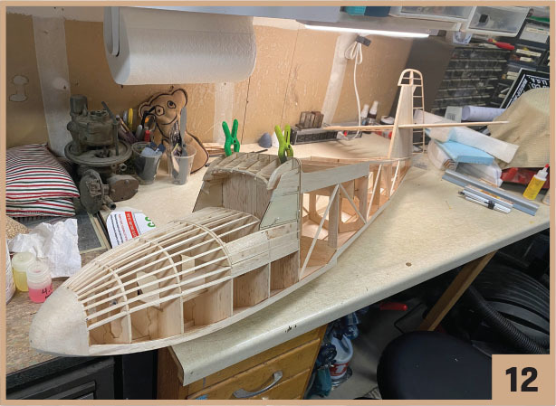
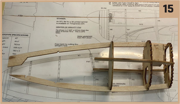
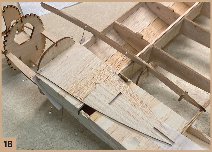
The Fuselage
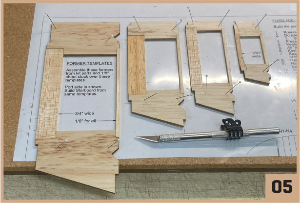
I like to begin the fuselage assembly by collecting all of the parts needed into a kit. Some of the formers and keels need to be preassembled. Taking these steps in advance will make the build flow more smoothly.
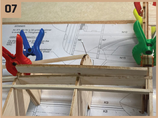
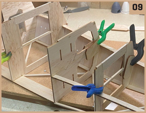
Begin construction by pinning keels K1 through K4 over the plans. Begin gluing the port A formers into place, working from front to back. All formers should stand perpendicular to the board. Tie the formers together by gluing keel K5/6 and wing saddle K7 into place. Add the 1/8 × 3/16 rear stringer to the upper corner of formers F8 through F12.
Add the hatch rails to complete the port side of the battery hatch. Glue lower rail K8 to formers F4, F5, and F6. Glue the upper rail to formers F4H, F5H, and F6H. Use the glue judiciously to make hatch removal easier.
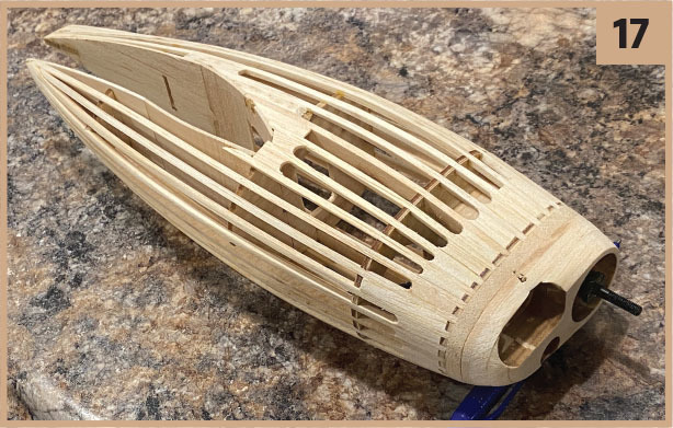
Sheeting the bottom of the hull while it is pinned to the board will ensure that the assembly stays square. The front hull, which takes the most abuse, is sheeted with 1/8-inch balsa. Sheet the rear section with 1/16-inch balsa.
All that is left now are some diagonal braces behind former F6. Once the fuselage assembly has fully cured, it can be removed from the board to begin construction of the starboard side. Start by gluing the battery tray into its slots. Now add the B halves of the formers, the starboard keels, and then sheet the rest of the lower hull in the same way as before.
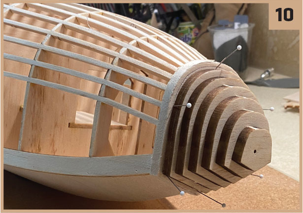
Add the servo tray and the wing bolt pad to the fuselage assembly. Now is a good time to add the handful of stringers to the nose. After they are in place, sand the front of former F1 flat to make a pad for the nose block.
Glue the stack of nose block parts B1 through B6 together after aligning them using the small hole that runs through each. Glue the stack onto the front of F1.
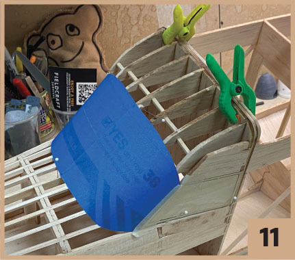
The last bit of the fuselage to be assembled is the cabin. Glue cabin formers C1 through C5 to former F6H. Use the side window frame to align C5—it is the only cabin former to be angled. Use the windscreen template to cut a plastic windscreen. Use scrap balsa between the cabin formers to form a frame for the windscreen.
This completes the basic assembly of the fuselage. The battery will be accessed by removing the cabin as a hatch. Cut the nose stringers between formers F4T and F4H and carefully remove the hatch. Add some locating pins and magnets to hold the hatch in place.
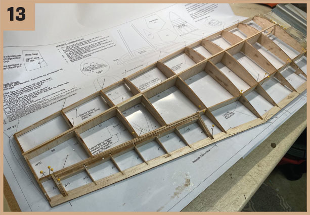
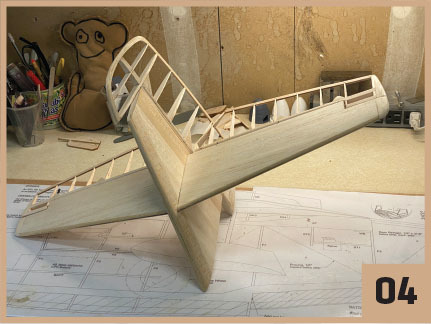
The Wing
Get the wing started by pinning the lower main spar and the rear main spar to the board. Carefully crack these parts, where shown, to enable the root ends to be lifted from the board as the ribs are installed.
Start gluing the ribs in. I installed W10 and W5 first to fine-tune the spacing between the spars and to lock them down where they were cracked. Fill in the rest of the ribs. All should stand perpendicular to the board except for root rib W1. Use the dihedral gauge from the plan to set W1’s angle.
Glue the trailing edge (TE) to the backs of the ribs. Crack the TE. Add the upper main spar and the shear webs between the ribs. Add the leading edge (LE)—this is the last part that needs a crack. Once it’s in place, flood all of the cracked joints with CA glue.
Install the aileron parts in order. A3 is a doubler to the rear spar. Don’t get glue between A3 and A4 because this will be the parting line of the aileron. Stack the two wingtip parts and glue them to the outside of rib W10.
Sand the assembly lightly where the upper sheeting will be located. Sheeting the assembly while it is still pinned down will prevent unwanted twist in the wing. The alignment feet under the ribs will set the proper amount of washout.
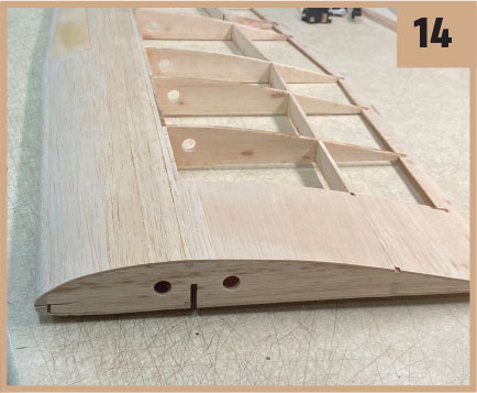
Once the sheeting has cured, the wing can be removed from the board. Epoxy float pads P1 and P2 to the underside of the wing. Don’t forget to add the scrap balsa pads for the bracing wire eyes like I did or you’ll be doing some surgery on the wing later.
Remove the alignment feet and give the underside of the wing a sanding. Add the lower sheeting. Sand the front of the assembly flat and glue on a LE of 1/4-inch-thick soft balsa. Sand the outsides of rib W1 flat and fit the plywood dihedral brace.
Now it’s time to join the wing halves. When the wing is lying upside down with the dihedral brace in place, it should be flat from tip to tip across the main spar. Once this is so, glue the wing halves together and epoxy the brace into position.
The Nacelle
The AMA version of the plans has two nacelle options. The base version is the original style that housed 200-hp inverted, six-cylinder Ranger engines. I like this classic look, but it’s a tight fit to get the motors, ESCs, and wiring situated.
Most full-scale Widgeons that are flying today have been upgraded, and many of those have been converted to Super Widgeons by MacKinnon Enterprises. The MacKinnon nacelle is quite a bit larger than the original Ranger nacelle. Either way you go, the two build similarly. Let’s get started with the Ranger.
Build up the cowling opening by stacking up parts N1 through N4 then build up the motor mount, as shown in the inset on the plans. Don’t worry about thrust angles—when built according to the plans, the nacelle will have the upthrust needed for the Widgeon to unstick from the water, and counterrotating propellers will cancel torque effects. Epoxy the motor mount to firewall N7 now because it is tough to get to once the nacelle is assembled.
Fit nacelle parts N5 through N10 together. These parts will largely self-assemble, but confirm that side keels N9 are parallel to one another and that formers N6 and N7 are perpendicular to the insides of the side keels. Once this is so, glue all of these parts together except for lower keel N10.
Remove N10 and set it aside for now. Preassemble upper wing pad N11 and tape it to the top of the wing. Waxed paper between the pad and the wing will keep things from sticking. Now glue former N12 to N11.
Fit the nacelle assembly to the wing. The front edge of N11 should be even with the LE of the wing. The TE of upper keel N5 should engage former N12 and the back of pad N11.
Flip the wing upside down. Tape lower wing pad N13 to the wing’s underside with another waxed paper spacer. Glue it to the back of N8. Glue formers N14 and N15 to lower keel N10 and attach these parts to the nacelle assembly to hold everything together.
Finish the nacelle by adding the 1/8-inch square stringers. Let the nacelle cure fully then slide it off of the wing for covering.
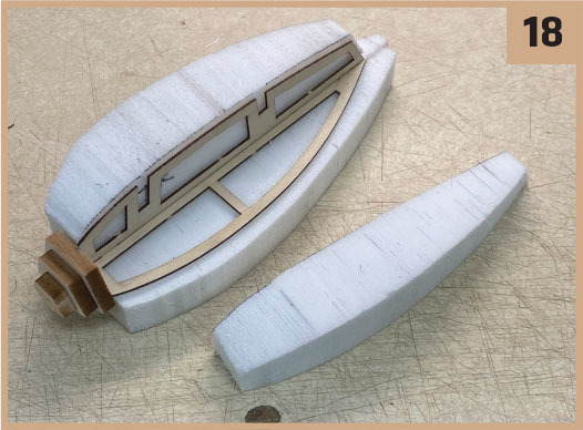
The Floats
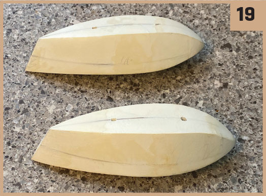
The last items to be assembled are the wing floats. These are comprised of a light plywood frame and a soft balsa nose. The spaces between the frame parts are to be filled with foam, and then shaped. The Widgeon’s floats have a pentagonal cross-section, making them easy to shape.
Glue side frames P3 and P5 to vertical frame P4 so that the side frames are perpendicular to P4. Stack and glue float noseblock parts P6 through P8 together, and then glue the assembly to the front of the float framework.
Fill the quadrants between the plywood float frames with light foam. Use the supplied templates and the plywood frame as guides while shaping the floats. I used a rasp followed by 60-grit sandpaper to make short work of this step.
Wrapping It Up
Whew—that was a lot! By now, you have a good feel for the size of this model. It’s not Giant Scale, but it is significantly larger than the Goose.
Next month, we’ll install servos, finish the control surfaces, and get the Widgeon ready to cover. Until then, I hope you can get out and enjoy some fall flying before winter sets in.
SOURCES:
Manzano Laser Works
60″ Grumman G-44 Widgeon
RCGroups
www.rcgroups.com/forums/showthread.php?4617725-60-Grumman-G-44-Widgeon


Comments
Add new comment