PHOTOS BY THE AUTHOR

Vendor/Parts List:
OSMW:The Fifty Six model kit; most of the hardware
Hitec RCD:Four HS-311 servos
Du-Bro:2.25- and 2.5-inch chrome wheels; 30-inch Micro Pushrod system; Kwik Sand; Kwik-Links; Electric Flyer Hinge Tape
Dave’s R/C Electronics:Y harness; SafeStart
Spektrum RC:DX6e transmitter; AR6200 receiver
Innov8tive Designs:BadAss 2820-1080 Kv motor; BadAss Rebel Series 65-amp ESC
APC Propellers:10 × 5E propeller
Flight battery:3S 2,600 mAh LiPo
Horizon Hobby:UltraCote covering (one roll of transparent red; scrap for gold trim)
You have had your foamie airplanes, and now you want to do something different. Maybe you want a throwback to what some would call "the good old days," where you would buy a kit with printed plans, follow an instruction booklet, and select the motor, wheels, and other parts that you want to use on it. You even got to choose the covering/color scheme!
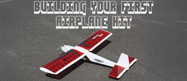
To illustrate how this is done, I selected a veteran kit that is very simple and easy to construct. In fact, thousands have been built. It can be powered by either electric or glow, and the color schemes are almost endless for whatever you wish to use. This kit is designed and manufactured by Old School Models Works (OSMW), and it’s called the Fifty Six.
About the Fifty Six
EAA has selected the Fifty Six as the dedicated basic trainer for its Young Eagles program. Various EAA chapters use these kits to train aspiring aviators about the basics of aeronautics, which are the same for full-scale as they are for models. The kits teach students to follow instructions as well. EAA even has its own color scheme for the model.
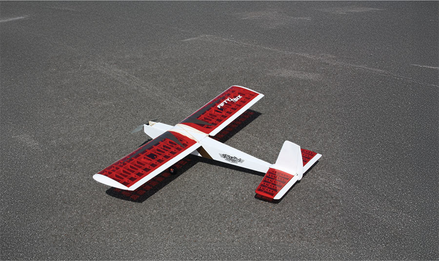
You will probably be the only one at the field with a Fifty Six. It is based on the Carl Goldberg Falcon 56 from many years ago, but this kit has laser-cut parts and a few tweaks to accommodate modern radio systems. Choose your power system, color scheme, wheels, and so on to make it a unique model for yourself. The wing is even held on with rubber bands that are made in the USA, just as it was 50 years ago.
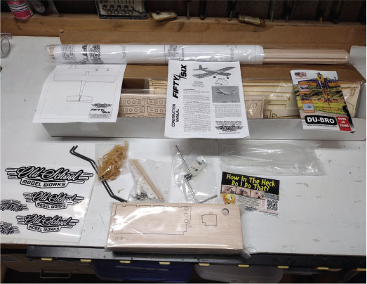
The kit comes with the spars and sheeting, which are about the only parts you need to cut. The basic tools you will need are an X-Acto knife, extra blades, a sanding bar, waxed paper (from the grocery store), T-pins, a small hobby saw, CA glue, a sealing iron, and a straight board on which to build the model. I use an old door blank with sheetrock on top. Just make sure that it’s level across the top. Most of the tools listed here are available from Du-Bro, and the rest you can pick up at your hobby shop, Lowe’s, or Home Depot.
Getting Started
Start with the instruction booklet and the plans. You can select your motor, ESC, batteries, and radio gear (including servos and receiver) from suggestions in the instruction booklet. The website even has a section for electric components that are proven to work with whatever kit you select.
Lay out the plans on your building board and read the instruction booklet beforeyou start building. Don’t take the parts off of their sheets until you are sure of what you need first. All of the parts names are marked on them or on the parent wood sheets. The instruction booklet also has checkboxes so that when you have to stop for the evening, you will know where you left off.
There are also more than 18 short videos on the OSMW website with tips for new builders about covering, soldering clevises, making your own pushrods, and much more, so check those out.
In reading the instruction booklet before I began, I noticed a QR code for color photos of the build that are available online. If you have a smartphone, just scan the QR code and all of these photos will pop up; you can download them as well. They are well worth the effort!
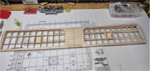
Building the Wing
Start building with the wing, which uses the largest sticks and parts of the build. Do not start with smaller parts such as the elevator or rudder; otherwise, you might not have enough long pieces left to finish the model. Lay out your plans on the building board and cover them with waxed paper over where you will be gluing the parts together.
Assemble the main spar for the wing half. Note that you should not align the scarf joints in the same place but rather opposite to each other for the front spar. I used medium CA glue for this and most other steps. After gluing the pieces together, add the top and bottom sections of the spar and gently sand them. Be sure to sand off the corner of the spar where you put it through the ribs. This will make it much easier. Follow the directions about not gluing the spacers near the center wing ribs because these will be taken out later for the center spar brace.
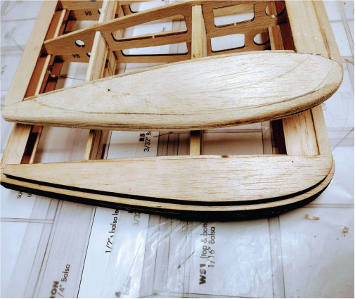
After adding the ribs to the spars (except for the inner ribs), add the leading edge (LE) and trailing edge (TE) to the length of the wing half. I assembled the wingtips and added them to the outer ribs before joining the wing halves. After getting the wing halves as close as possible to the same shape, it’s time to join them. Similar to all other parts, test-fit the spar braces and the wing halves.
When you are satisfied with the fit, epoxy the spar brace into one wing half. Work it back and forth easily, fitting the brace into the slot. Be sure to not let epoxy dry on the innermost rib, to which you need to fit the other wing half. Just wipe any excess epoxy off with a tissue. Add the other wing half and hold it until it is dry. Wipe away any excess epoxy on the outside of the wing before the epoxy cures.
Tail Surfaces
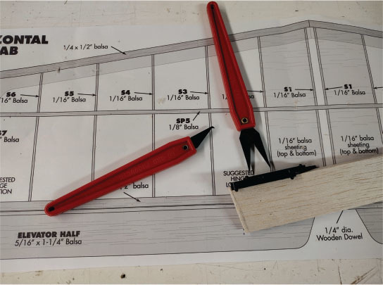
Assemble the vertical stabilizer and wipe off any excess CA glue. Lay the parts on a flat surface to ensure a straight assembly for the model. The horizontal stabilizer is made of 1/16-inch ribs and a balsa spar. The ribs are delicate, and care should be used in their assembly to the spar. The spar runs through the ribs and you have to glue them in place. I recommend using medium CA glue on all of the steps for the tail surfaces. You need the quick-setting glue to guarantee that you are not letting the rib wander on the spar position.
After adding the LE, TE, and sanding, add the sheeting on the horizontal stabilizer next to the vertical stabilizer. Cut 1/16-inch balsa sheet for these four parts. Be sure to fit the front and back of the sheeting into the stabilizer. Add the block at the rear bottom of the stabilizer that fits into the fuselage, and you will be done with this assembly.
I wanted to add transparent red covering to both the tail surfaces and the wing. The ribs have a dark color on the top and bottom where the laser did its job. Sand these areas very gently with an emery board—you just want to take the dark color off and not any balsa.
Fuselage
Before you start the fuselage, you should decide whether you are going to use electric power or glow power. There is a difference in the motor mounts for the two types of power, and it makes a difference with the length of the plywood in the nose. In this example, I went with the electric power setup, including the modification in the lower front fuselage to add a small scoop to bring in cooling air.
As with the other parts of the kit, start with the subassemblies. Continue to dry-fit all of the parts of the kit, especially the forward parts of the fuselage. Double the firewall with epoxy and punch out the hole that will be used later to run the power wires to the ESC. Note that the marks on the front of the motor mount are for the nose gear.
The downthrust angle and the right-thrust angle are built into the mount and the sides of the fuselage. Look for the circles on the parts and be sure to dry-fit the forward fuselage side to this box and the motor mount. If you look straight down, it should appear that the motor mount has a slight down angle and an angle a couple of degrees to the right. The forward inner parts of the fuselage fit so tightly that it reminds me of building with Legos. Medium CA glue is still needed, but they fit really well.
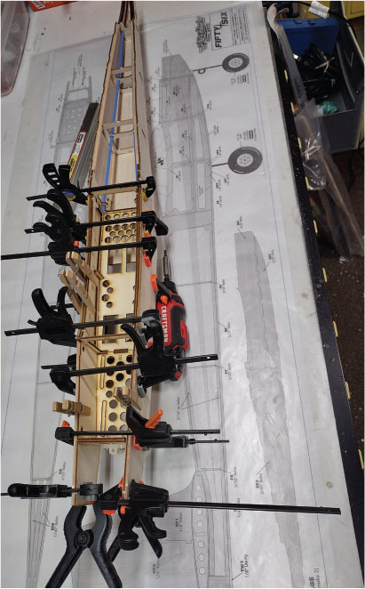
As with other parts, the fuselage sides lock into place with medium CA glue. Be sure to use a paper towel or tissue to wipe off excess glue if there is any on the outsides of the left- and right-side halves.
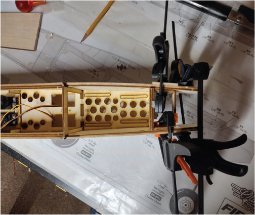
The fuselage builds quickly. After assembling the sides, leave the top sheeting open to install the pushrods for the elevator and rudder. There are balsa cutouts located in the fuselage to install the pushrod tubes. Glue these into place with epoxy. After securing the tubes, add the top sheeting, which locks in with the precut tabs.
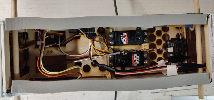
If you choose to use a two-stroke glow engine with this model, don’t overpower it. A good O.S. .25 should be plenty of power. For my electric variant, I mounted the motor on the electric firewall in the kit. I used 2-56 socket head bolts and blind nuts. Make sure to leave enough room for the nose gear when you mount the motor. Run your ESC wires to the motor and anchor the ESC in the fuselage with Velcro. Add Velcro for the battery as well.
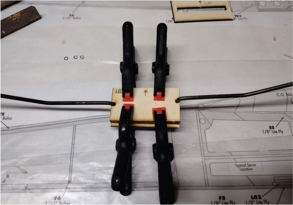
Add the bottom front sheeting after you’ve assembled and installed the main gear blocks. After all of the sheeting is installed, it’s time to sand down any of the tabs that are sticking out of the sides and any sharp edges on the fuselage. Install the servos and other hardware as listed in the instruction booklet.
Covering
You want to cover the model with a very visible color scheme. An example of this would be white UltraCote and another color such as orange, red, green, or yellow. I recommend staying away from dark colors such as navy blue, gray, or black. They tend to make any model harder to see and control in the air, especially if you are still learning.
Experiment with the temperature control on your sealing iron. UltraCote uses a lower heat setting than the older MonoKote. If you have a heat gun, be absolutely sure to keep it moving while shrinking the covering. If you stop in one area, you will melt a hole very quickly!
As you cover the wing and tail surfaces, cover the bottoms first; if you goof, it won’t show as much. Do the same with the fuselage. Cover the bottom and work from back to front.
For electric power, now is the time to add the cooling holes in the bottom rear of the fuselage, as well as the scoop under the forward fuselage. It’s a pretty simple modification and it will ensure that your ESC doesn’t overheat. This is covered in the instruction manual and photos.
Use thin CA on the supplied hinges. I like to use a paper towel on the back side so that I do not get any glue on the top surfaces of the wing. When all of the hinges are in the ailerons, test-fit these into the wing’s TE. Glue them in place when you are satisfied. I also add Du-Bro’s Electric Flyer Hinge Tape to the small gap on all control surfaces. No flutter is a good thing!
Flying
Check out all of the control surface throws as per the instruction booklet before flight, and make sure that everything is moving in the correct direction, or, as I call it, "The Dummies Guide to Control Settings." My model was set up with the same recommendations from the kit manufacturer for flight: 1/2 inch up/down on the ailerons with 25% exponential; 3/8 inch up/down on the elevator with 20% exponential; and 1 inch left/right on the rudder with 15% exponential.
My battery selection was a three-cell 2,600 mAh LiPo pack. I mounted it as close to the firewall as possible and the model balanced there. You can use larger packs for more flight time, but this is what I had on hand. The throttle is quick and responsive. Using the SafeStart system from Dave’s R/C Electronics gives you another level of safety. The motor isn’t allowed to start unless you press in and hold the button on the side of the fuselage, which will turn from red to green to signify that it’s ready and powered up.
I used a standard Spektrum six-channel receiver and a Spektrum six-channel transmitter. It’s nothing fancy—no gyro or autopilot. Those features are just not needed to fly this airplane.
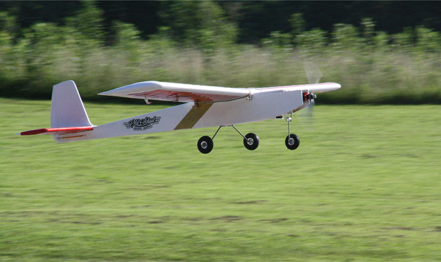
On takeoff, the model climbed quickly and was taken up to what we refer to as "three mistakes high." I added two clicks of elevator trim and a click of aileron trim. After that, I tried some basic maneuvers, such as a loop, a roll, and then a touch-and-go, and finally a landing. On landing approach, just let the airplane mush in and it will pretty much land itself. The nose gear makes ground handling easy and quick; there were no problems there at all. The Fifty Six is just an honest, straightforward design.
If this is your first model, have an instructor or someone you trust trim the model for you. Check and recheck everything to make sure that it’s ready to fly and you should be good.
This was a fun build, and the color scheme really shows up well in the air. The Fifty Six should give you years of enjoyment, and you might even teach another person to fly with it. I can see this as a go-to airplane to keep the fingers limber! Enjoy!
SOURCES:
Horizon Hobby


Comments
Add new comment