The Control Line (CL) model that is flown today traces its roots back to the 1940s. Some of the traditional ways of setting up a CL model have not changed, but the models are now larger and have taken advantage of new technologies that are available.
After World War II, the ignition engine was typically used and you didn’t have throttle control. You would fly until you ran out of fuel, and then you would land. CL is still being flown this way in many of the events.
Starting in the 1950s, the small CL Scale models became larger as larger engines were made available. The development of the glow engine with a carburetor that allowed the engine to go from idle to full power played a big role and was just one of the first items that led to other changes. The three-line handle, down-the-line electronic controls, and then the use of 2.4 GHz radio control for CL Scale and Navy Carrier transformed the hobby once again. Electric motors add another reason why the models are very different from the typical models that were flown in the late 1950s or early 1960s.
The evolution of the glow engine affected how the CL model changed throughout the years. Several significant shifts within the hobby have allowed CL Scale models to become larger and operate with more mechanical features, such as a throttle, flaps, retractable landing gear, and bomb drops, among other features.

If you have an engine available with a carburetor, you need something to control the throttle. The threeline handle filled that role to operate those newer engines. Converted 72 MHz RC technology was used for down-the-line electronic controls, and 2.4 GHz RC technology played a role in what happened next. Now we have electric motors and electric retracts available for CL Scale models. The modern CL Scale model looks more like an RC model but with a bellcrank to control the elevator.
Glow Engines Are Changing
At first, the ignition engines that were used for CL models required a spark plug and other items to support their operation. In 1947, Ray Arden developed the glow plug, which dramatically changed the engines that were available. The 1959 K&B .45 RC engine had a carburetor with an exhaust baffle.
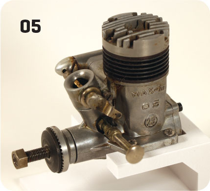
The timeline for the O.S. brand of glow engines shows that the 1958 O.S. Max II RC engine had the traditional fixed needle-valve with a butterfly valve on the top of the venturi and an exhaust baffle. Those 1958 O.S. engines showed what was coming.
Over time, the exhaust baffle went away and the typical O.S. engine just had the carburetor. In 1984, the O.S. 35FP engine was introduced with a carburetor that had the needle-valve built into it; it did not use the exhaust baffle.
In 1962, the Veco 45 engine had a full carburetor that was similar to those flown today, except it had an exhaust baffle.
These are just a few examples of how the engines have changed throughout the years. This article does not discuss the development of engines; however, the engines that could throttle from idle to full power led to items such as the three-line handle and bellcrank.
If you have been in this hobby long enough, you have seen many updates with how you power a model airplane. Ignition engines were replaced by glow engines, and then four-stroke glow engines became available—they sounded very different from the two stroke glow engines. Within the RC world, the gasoline-powered engines started to become smaller and more available.
Glow-powered turbines were developed to simulate jet engines, but these were replaced with the smaller jet turbines that are now available. Brushed electric power became available with the Astro Flight motors using NiCd battery packs, and the LiPo battery-powered brushless electric motors have had a big effect on the hobby. All of these products have been used on CL Scale models.
Three-Line Control
The three-line handle and bellcrank were developed to allow pilots to operate the throttle on the model with a special handle that worked with a specific three-line bellcrank. A 1957 American Modeler magazine issue discussed how this was introduced by the J-Roberts Model Manufacturing Company.
This bellcrank would keep equal line tension across all three lines, regardless of whether you were idling or at full power. These systems are still being flown today, but they only operate one item: throttle control for engines with a mechanical carburetor. If you lose line tension, you do not have throttle control with the model. The third line must be a precise length for the system to work correctly.
AMA Hall of Fame 2006 inductee Frank Beatty was building a new model with an engine that had a carburetor and a separate fuel tank that sat behind the engine and put the three-line bellcrank behind that. Because of the size of the items, he had to make the model larger to have everything fit into the fuselage. This model had a wingspan of close to 45 inches. Someone told him that he was building a Giant Scale aircraft! The size of the CL Scale models has gotten even larger since that time.
If you double the size of any model, the wingspan is twice as large, but the wing area is four times larger. The increased wing area allows for a higher wing loading. Wing loading is defined as the number of ounces per square foot of the wing area. The smaller the model, the lighter the wing loading needs to be. The larger the model is, the more the wing loading can be increased, and it will still fly correctly.
If you add a 2-ounce servo to a small model, it might have a severe impact on how well the model will fly, but if you add the same 2-ounce servo to a larger model, you might not even notice a change with its flight performance.
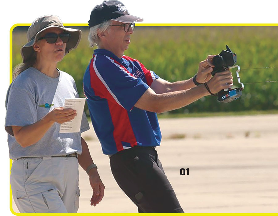
Frank also flew a scratch-built PT-22 from his own plans, but it had a special Fox 25 engine in it that was modified by Clarence Idoux. It had a metal butterfly valve in the venturi that would move to throttle the engine with a three-line system. Frank flew this model in 1961 and got a lot of attention when other pilots saw this and wanted to know more.
The three-line bellcrank and handle designed for the CL model was one of the major inventions that changed the hobby. The next two inventions, however, were designed for RC but also had a major impact on the CL modeling community.
The first was the 72 MHz RC units that were being converted to down-the-line electronic controls. The second was the 2.4 GHz RC units that were allowed to be used in CL Scale and Navy Carrier competition beginning in 2013.
72 MHz Radio Conversions: Experimentation
CL Scale and Navy Carrier have been using kits and equipment designed for RC for years. One item that was modified for CL use was the 72 MHz RC transmitter and receiver. The CL Scale rules prior to 2013 stated that radio control could not be used to control any functions on the model. This was because it was not uncommon for a CL flying site to be near one for RC flying, and any interference on the 72 MHz channels would be a big problem.
The 72 MHz transmitter has a circuit board that creates the radio signal that the receiver picks up. It then controls the servos to match the commands from the transmitter. These early conversions removed this portion of the transmitter and receiver and replaced it with two wires: signal and ground. The length of the two wires did not matter since it was sending a signal and ground. There was no voltage in these two wires.
This became known as down-the-line electronic controls, where the two flying lines were insulated to make sure that the two wires did not touch and short out. The same two insulated flying lines controlled the two-line mechanical bellcrank for the elevator, but they also carried the signal and ground through two electronic connectors.
When I flew with this system, we used nylon-coated fishing leader intended for saltwater fishing, and it had connectors on both ends of the lines. This system worked quite well, even though you had an electrical wire coming from a transmitter that plugged into the flying lines. There was also an electrical connector from the flying lines to the receiver.
When I first started flying CL Scale in 1988, I found references to this down-the-line electronic-control method, but information was not commonly available about how it was being done. I wanted to convert my Ace R/C three-channel transmitter and receiver, but I couldn’t find any published information. I contacted the company and it showed me how.
Down-the-Line Becomes Mainstream
After I converted my Ace transmitter and receiver for down-the-line electronic controls, I started to document how I was doing this to make it available to others. I was at the Whittier Narrows CL flying site in the Los Angeles area one day and someone asked me a question about it when they saw the test model.
This person knew that we were flying with down-the-line electronic controls and asked me whether I was willing to share the information. At this point, I realized that I wasn’t the only one looking for this information, so I got busy writing it up and sent it to Bill Boss, Model Aviation’s "CL Scale" columnist at the time, and also sent articles to Model Buildermagazine.
It took a few years, but down-the-line electronic controls became more popular to control the throttle on CL models. Grant Hiestand, Merle Mohring, and I continued to look into other RC devices to see whether those could be used. We did find other items and tested them.
Pilots would take an existing 72 MHz radio system and send it out to be modified for down-the-line controls. These radios were permanently converted for CL use. Not all of the features of the transmitter were affected; just the radio-frequency boards for the radio signal, which were bypassed in the transmitter and receiver.
ZTRON Infrared Controls
The ZTRON infrared control system was not an RC or a mechanical system like the three-line system, but it used infrared signals to control the throttle. You would wear a hat that was pointed toward the model, and then, on the inboard side of the fuselage, there would be a receiver that would be in line of sight with the hat that the pilot was wearing. I flew with this system; it worked, but if the transmitter units on the hat that was worn were not pointed at the model, it might lose its connection. This system was not widely used, and I haven’t seen one since.
Windy Urtnowski flew the CL Stunt pattern with one of these systems in 2001. He got into the top five at the Nats that year. He was flying a four-stroke-powered Stunt model with this so that he could throttle when needed, and then set the throttle to the desired flight speed that he wanted. The following year, the ZTRON system was outlawed in the CL Stunt rules.
JR Transmitter With DSC
Some 72 MHz transmitters manufactured by JR PROPO had a feature that was designed for RC pilots, but it was perfect for what we needed for our CL Scale models. On the back of the transmitter, there was a jack. It looked like a charge jack for the battery, but instead, it was the DSC jack.
DSC stands for direct servo connection. You would plug in your DSC wire and it would turn the transmitter on. You would then plug that wire into the charge jack connector on your on/off switch harness in the model. You did not use the on/off switch on the front side of the transmitter to turn it on.
When you plugged the DSC cord into the transmitter, it would not create a radio signal. You would control the servos on your RC model in the same way as you would if you were transmitting a radio-frequency signal. In DSC mode, it was hard-wired to the receiver.
When I flew with this system, I would remove the radio-frequency plug from the transmitter, and then plug one half of the DSC cord into the transmitter, which would be plugged into the flying lines at the handle. The other half of the DSC cord would go from the flying lines to the receiver at the model through the charge jack interface on the switch harness. For this feature to work, you had to have the deluxe on/off wire harness that had all three wires for the connectors.
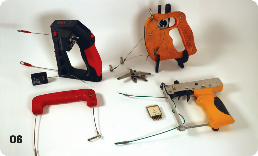
Bill Young Handle
The Bill Young CL handle was a down-the-line handle that had a built-in battery and trigger, and the electronics were built into the handle. The two insulated flying lines would attach to the handle just like a Stunt handle. There were toggles built into the handle that could operate other channels. This sold quite well in the 1990s, but I haven’t seen anyone fly with one of these recently.
Servo Driver
The Custom Electronics servo driver was designed to allow RC pilots to test a servo. The unit had a throttle stick and battery, and three connections for the servo: power, signal, and ground. We were able to use this unit to control the throttle. We used the servo driver to send the signal and ground to the model, and then we put a servo and a battery in it. This down-the-line system worked great for aircraft that only needed throttle control. The ground had to be common between the servo driver and the model and have insulated lines.
Dave’s R/C Electronics has a product called the Turbine Tester that behaves in the same way to control a servo when you turn the dial. I can hold this small item in my left hand and operate the throttle, but I have to use insulated lines with it.
Pilots had several choices, including modified radios, the Bill Young handle, a servo driver, and JR DSC systems, from which to choose. They all worked so that each pilot could pick what they liked best. However, there were more changes coming that would transform the throttle control system once again, one of which was 2.4 GHz radio technology.
2013 Rules Change: 2.4 GHz Approved for CL Scale and Navy Carrier
In 2013, the CL Scale and Navy Carrier rules were changed to allow 2.4 GHz to be used to control everything except the elevator. Fast-forward 12 years later to 2025 and you will see that 2.4 GHz has been widely adopted and is the main system for throttle control for CL Scale and Navy Carrier. Using 2.4 GHz eliminated the channel interference problem with the 72 MHz radios at RC flying sites.
Just like any other RC equipment, this can be used with a CL model without any problems. I stopped using my down-the-line electronic controls in 2013, and then I purchased a traditional 2.4 GHz transmitter and receiver.
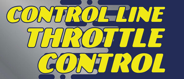
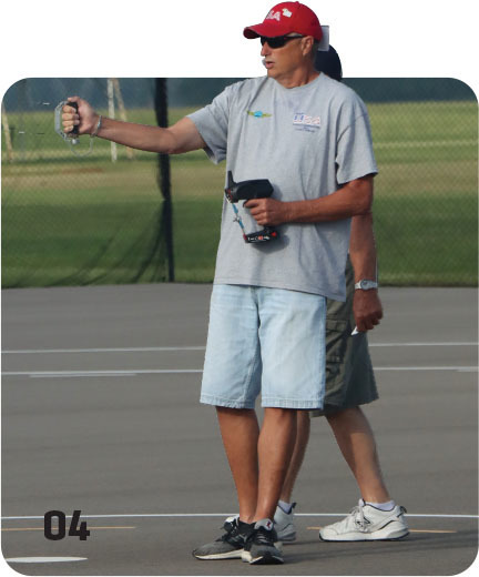
I stopped using the insulated lines and now fly using a typical Stunt handle with simple braided lines. I hang the transmitter on my belt and operate the throttle stick and toggles by feel. It sounds difficult, but with a little practice, you get used to it.
The RC 2.4 GHz devices that are designed for RC cars can also be used. Pilots have added structure to them to make them into CL handles with which to fly. You can also fly with a Stunt handle; your other hand operates the trigger on the RC car transmitter for the throttle.
LineMaster Handle
Carlos Diaz created the LineMaster 2.4 GHz CL handle in 2024. A prototype was brought to the 2024 Nats and it quickly attracted the attention of the pilots flying CL Scale; however, it was not yet available at that time. It was made available for sale in 2025.
The five-channel handle has a trigger for the throttle control and four toggle switches. This handle’s configuration is very similar to the Bill Young handle, but the big difference between the two is that the LineMaster handle has model memory and endpoint adjustment, among other features.
I have flown two models with this system without any problems. Like any of these systems, though, you have to pick the one that you like best.
Conclusion
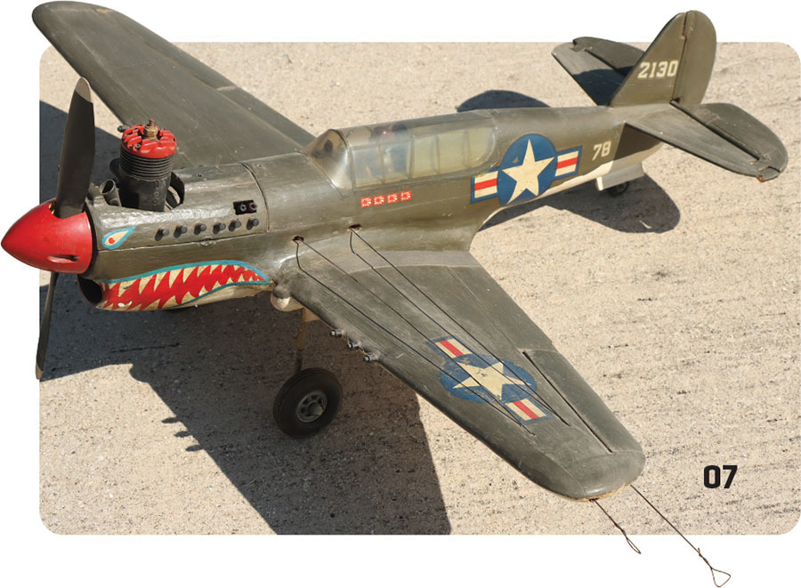
Regardless of which system you pick, they all work to control the throttle and the other features on the model. The conversion of an RC model to CL comes down to installing a bellcrank instead of an elevator servo, and then attaching a line guide to the model and adding some wingtip weight in the right wing.
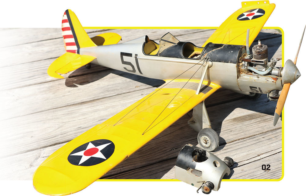
A large majority of the CL Scale models that are being flown today started out as RC kits. CL Scale models can only weigh a maximum of 20 pounds to meet the AMA rules. The allowable maximum weight for FAI F4B rules is lower.
Grant Hiestand flew a 20-pound Sig Manufacturing 1/3-scale Spacewalker in CL Scale for many years under the AMA rules. I have lost count of how many RC kits or ARFs I have converted for CL flying, including the 1/4-scale Sig Morrissey Bravo kit.
If you fly with 2.4 GHz, you can use off-the-shelf RC equipment, such as brushless electric motors, electric retracts, and servos, just to name a few, so next time you are at a swap meet, see if you can find an RC Scale model that is the right size for a CL model conversion.
In the AMA CL Scale Nats, there is an event called Fun Scale, where you can fly an ARF or a model built by someone else in the competition. Using your existing 2.4 GHz RC transmitter, install a bellcrank, a line guide, and a righthand wingtip weight. Everything else can be installed as though it’s an RC model.
Land softly!
SOURCES:
National Association of Scale Aeromodelers (NASA)
"The Modern Control Line Scale Model"
Model Aviation, June 2015
"Third Line Theme for Control Line Throttle"
American Modeler, August 1957
airplanesandrockets.com/resources/third-line-theme-aug-1957-am.htm


Comments
Add new comment