When asked how to balance multiple servos on a single flight control surface, many modelers reply, "Adjust them until no servo buzz is heard." Although this method undeniably works, there is a more optimal approach.
Why Servo Balancing Matters
Servo buzz is caused by the servos fighting each other and/or constraints from the mechanical installation. Buzzing leads to excessive current draw and premature servo failure. Although achieving a no-buzz installation is simple and quick, it is challenging to understand the current draw without measuring it or looking at telemetry.
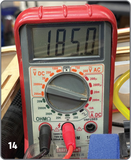
How serious of a problem is an excess current draw? Experimenting reveals that with two servos on a flight control surface, adjusting for no buzz results in a static no-load current draw of up to 180 mA per servo! With the nominal idle current for many servos around 30 mA, there’s an excess of 150 mA draw per servo!
We all check our flight packs after every flight, right? If not, we will surely check the battery pack capacity at the end of the day. Therefore, the effects of excess current draw are largely inconsequential—in part.The unanswered gremlin is excess servo wear!
If your airplane is equipped with telemetry, it can provide a wealth of information, including current draw, maximum current, battery capacity, etc. However, given the inherent latency and the necessity of frequently switching between servo adjustment screens and the telemetry screen, measuring current draw via telemetry is not recommended for servo optimization.
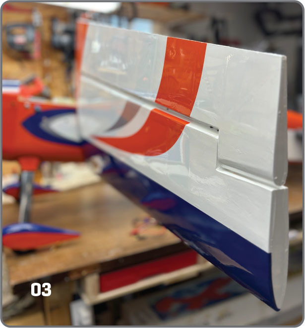

So, what is the process to achieve no servo buzz andoptimal current draw? I will discuss balancing two Hitec D950TW servos on one wing of an AJ Aircraft ARS 300 airplane with a 104-inch wingspan. The same method can be used on any control surface of any model.
Servo Balancing Tools
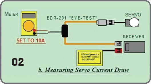
There are several methods for measuring the current drawn by each servo. One method is to connect a multimeter set to DC current in series between the servo and receiver. This requires custom connectors or using alligator clips to wire the multimeter in series. Another option is to use a DC clamp. Most modelers don’t own a current clamp, and few clamps have the precision needed to measure accurately down to 10 mA (the idle current found on some servos).
The method described in this article employs a current probe. The ElectroDynamics EDR-201 Eye-Test Current Probe is a quality and affordable tool. Using two current probes, connect both servos according to the ElectroDynamics diagram.
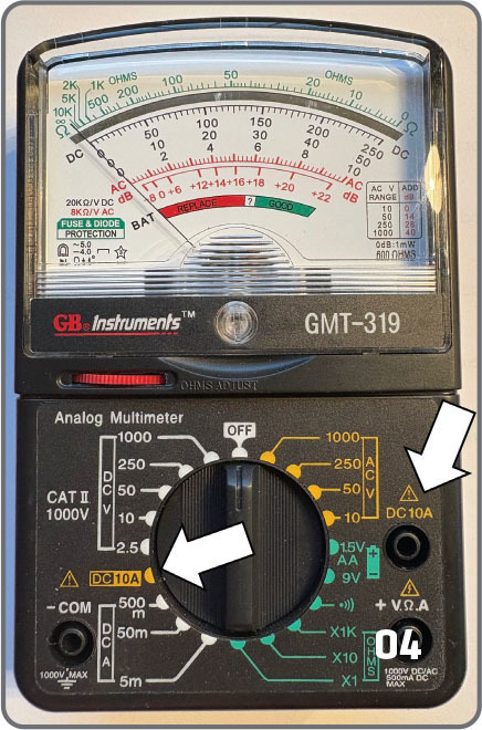
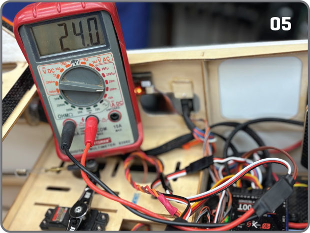
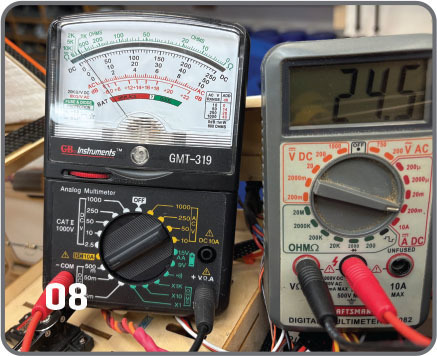
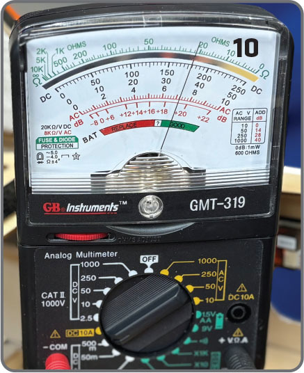
In this setup, I used a Craftsman digital multimeter with a maximum DC range of 200 mA and a GB Instruments analog multimeter with a maximum DC range of 500 mA. Analog multimeters make visualizing the fluctuating current draw much easier. Therefore, I recommend that at least one of the multimeters be analog. The current probe is connected to the multimeter’s standard jack in higher-resolution measurements.
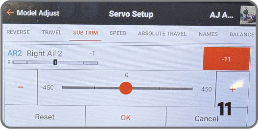
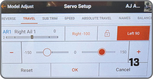
There are six variables to consider when setting up a servo: the mechanical linkage, the control horn hole (distance from the control surface hinge line), the servo arm hole, and three transmitter functions (subtrim, servo travel, and servo balance). When selecting the control horn and servo arm holes, choose a servo arm hole that matches the distance of the control arm hole to the surface hinge axis to achieve the recommended throws. Set servo travel to 150% in your transmitter to optimize the resolution of stick movement to servo rotation.
Servo Balancing Process
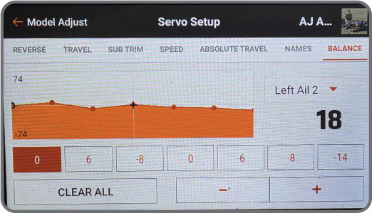
- Zero out or reset both servos (subtrim, travel limits, and balance) in the transmitter. In this test setup, I used a Spektrum iX14 transmitter.
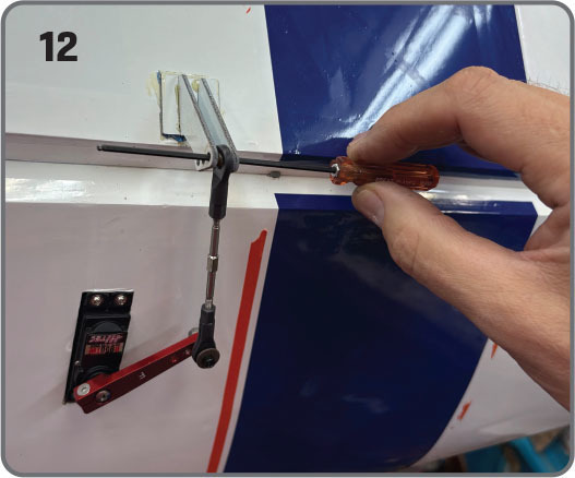
- Program the transmitter to achieve the desired aileron control throws with the outboard servo linkage disconnected.
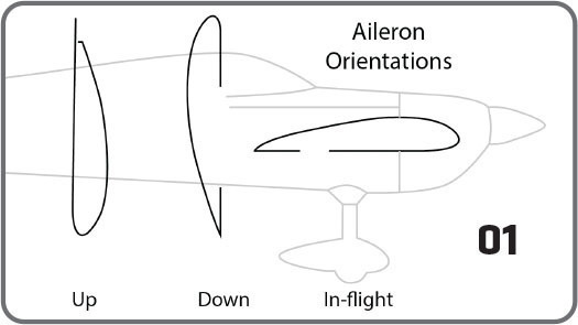
- To the greatest extent possible, rotate the wing perpendicular to the horizon so that the aileron is oriented upward and the wing’s leading edge (LE) faces downward. This setup mitigates the effects of the aileron mass if the servo is in its normal flight orientation or if the aileron is on the bottom and the LE is up. With this alignment, the servo doesn’t have to fight gravity; instead, gravity aids the servo’s movement. As an example, the inboard servo pulled 24 mA with the ailerons oriented as advised, 36 mA with the ailerons pointing down, and 42 mA in normal flight mode! Additionally, it is advisable to perform servo balancing indoors to mitigate wind load on the flight control surface.
- Ensure that the multimeter is set to DC 10A. The 10A connection is a separate jack on many multimeters, specifically designed to handle higher currents. As a precaution, start in 10A mode for all subsequent measurements. Most multimeters in higher resolution settings have a current limit of 200 mA. Exceeding this limit can blow the meter’s internal fuse, which is easily replaceable.
- Disconnect both servo linkages. (Note: This process starts by optimizing the inboard servo because the inboard aileron mass on a tapered wing is typically greater. In all of the succeeding tests, moving the transmitter sticks slowly will alert you to any excessive current draw that is experienced across the servo’s range because of mechanical reasons and mitigate excess current drawn when demanding a high-speed response from the servo.)
- Power on the transmitter and receiver and measure the idle current of the inboard servo at neutral.
- Slowly move the transmitter stick to achieve full left aileron throw at high rate.
- Slowly move the transmitter stick to achieve full right aileron throw at high rate.
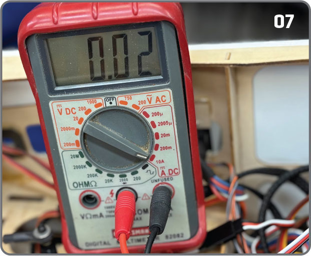
- If the current in all three positions reads less than the maximum high-resolution rating for your multimeter, it’s okay to transition out of the 10A connection. The high-resolution limit for the Craftsman multimeter that was used in this setup is 200 mA. Exceeding the high-resolution setting will likely blow the multimeter’s internal fuse. I recommend that you have a few replacement fuses on hand. The servos in my example pulled 24 mA at idle.
- Measure the current draw of the outboard servo (with the linkage disconnected) at neutral, full left, and right throws at high rate.
- Reconnect only the inboard servo linkage.
- Mechanical ly adjust the servo cont rol linkage until the servo pulls the same neutral-position idle current that was recorded when the linkage was disconnected.
- Ensure that the multimeter is set to the 10A setting.
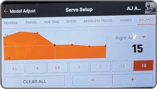
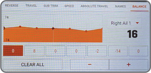
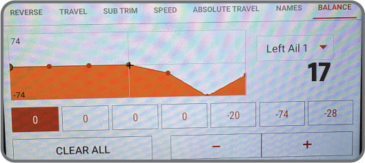
- Slowly move the aileron stick full left. The current draw should remain less than 500 mA unless you are moving the stick quickly. The D950TW servos that were used in this test setup rarely pull more than 200 mA during this step. Ideally, the current drain at full throw should be nearly the same as when it was measured with the disconnected linkage. If not, investigate for binding or other impediments. When the aileron stick is slowly swung to full input, it is possible to observe higher current draw regions. Depending on the magnitude of the draw, these hot spots can be remediated using the Balance function in the transmitter.
- Repeat the previous step, moving the aileron control full right. Adjust as necessary.
- Slowly swing the aileron stick full left to right, verifying minimal current drain.
- Move to the outboard servo. Keep a multimeter connected to the inboard servo. Constant monitoring of the current draw on the inboard servo is required while setting up the outboard servo.
- Turn off the receiver.
- Set the multimeter to the 10A setting and turn on the airplane power.
- Measure the idle current of the outer servo at neutral.
- Adjust the linkage mechanically to achieve the same idle current that was previously measured. Make small adjustments with subtrim as desired. Be sure to also monitor the inboard servo current to ensure that it does not change while adjusting the outboard servo.
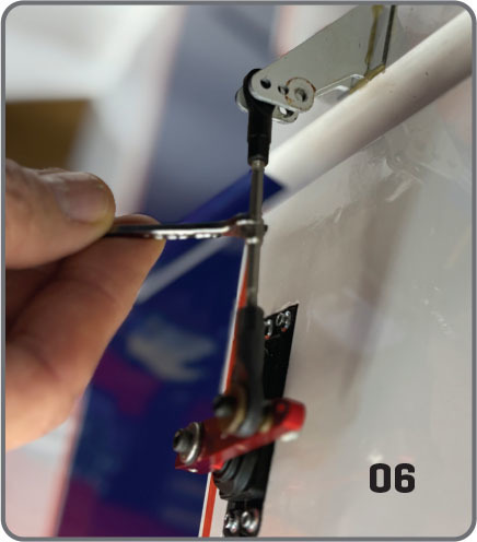
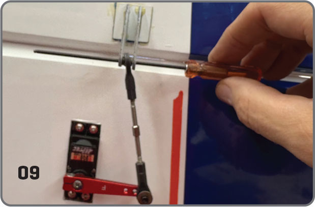
- Check the neutral servo centering on the flight surface control arm by inserting a rod. Mechanically adjust the length of the control linkage until a rod (ball-end hex driver or a similar tool that is slightly smaller than the diameter of the attachment bolt) slides freely through the control horn and ball link. Attach the outboard servo linkage to the control horn and measure the current.
- Because the current draw has slightly increased from the level that was measured when disconnected, adjust the control linkage to achieve the idle current recorded when disconnected. Alternatively, you can adjust the outboard servo using the transmitter subtrim. Ensure that the inboard servo’s idle current remains unchanged. While optimizing the servo current, you might need to readjust the inboard servo using the Balance function in the transmitter.
- Choose 10A on the multimeter. Disconnect the outboard servo control linkage. Push the transmitter stick all the way to the left.
- If the control linkage is not centered in the control horn at full travel, adjust the servo travel in the transmitter until a rod slides freely through the control horn. Do not adjust the subtrim or mechanical control rod linkage. Measure the current. Verify that the inboard idle current does not change.
- Slowly move the aileron control stick on the transmitter from neutral to full right and repeat the previous step to achieve the minimal current draw.
- Slowly move the aileron stick full left and right. In my experience, the current draw should remain less than 200 mA unless the stick is moved quickly. If high-current spots are discovered, they can often be remediated by adjusting the Balance menu in the transmitter.
Conclusion
I hope you will find this information useful and have a better understanding that buzzing can lead to excessive current draw and premature servo failure.
SOURCES:
Spektrum RC


Comments
Add new comment