Build your own Flying Aces Club Jumbo Scale competition aircraft
By Mark Fineman
Photos by the author
As seen in the July 2012 Model Aviation.
By the late 1930s, Italy held many world aviation records, most famously the absolute world speed record for seaplanes with the Macchi MC.72. Yet the country’s vainglorious dictator, Benito Mussolini, wanted more, particularly sport airplane records, then held primarily by Germany.
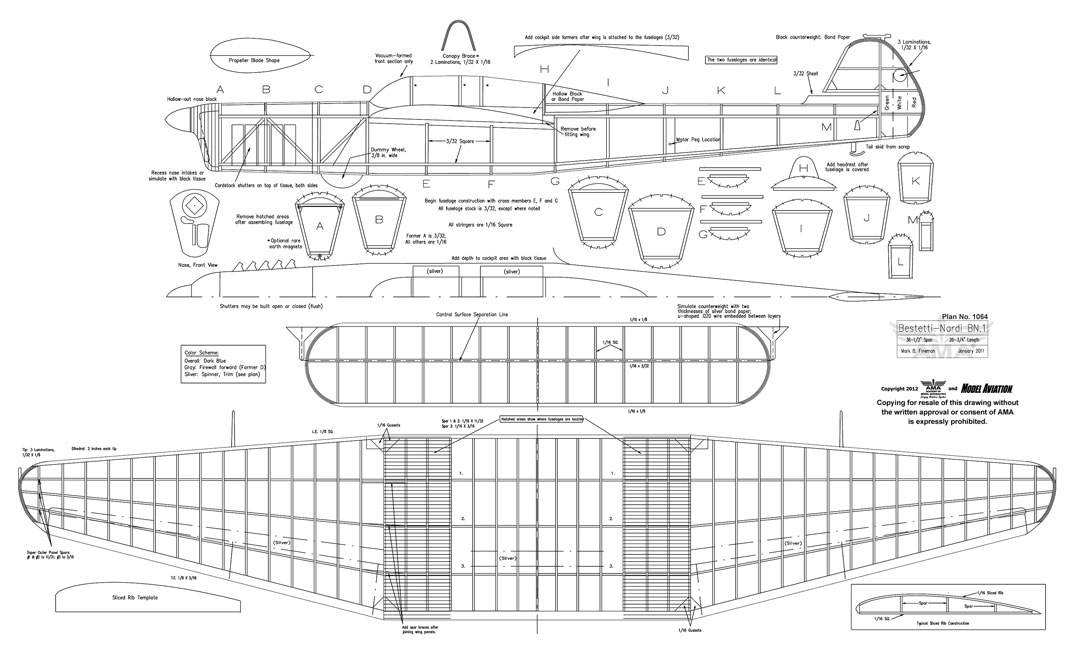
Engineer Pierre Luigi Nardi designed an unusual twin-fuselage light aircraft to be powered by two inverted Alfa Romeo 115 engines, built by the Bestetti firm, and ultimately to be designated as the Bestetti-Nardi BN.1.
The shoulder-wing, single-spar aircraft was of conventional construction: primarily plywood with fabric covering. It could be operated from either of the two cockpits.
Flight tests, which began in 1940, revealed instability that necessitated redesigning the tail, after which it proved to be dependable in the air. By that time, World War II had begun and any hope of making record flights was dashed. After scores of flights by Bestetti-Nardi, the airplane was handed over to the military, but proved unsuitable for a military role.
The aircraft was likely destroyed in 1943. The BN.1 carried a civil color scheme of overall dark blue aft of the firewall, with aluminum trim. Rudders were the regulation green, white, and red Italian tricolor.
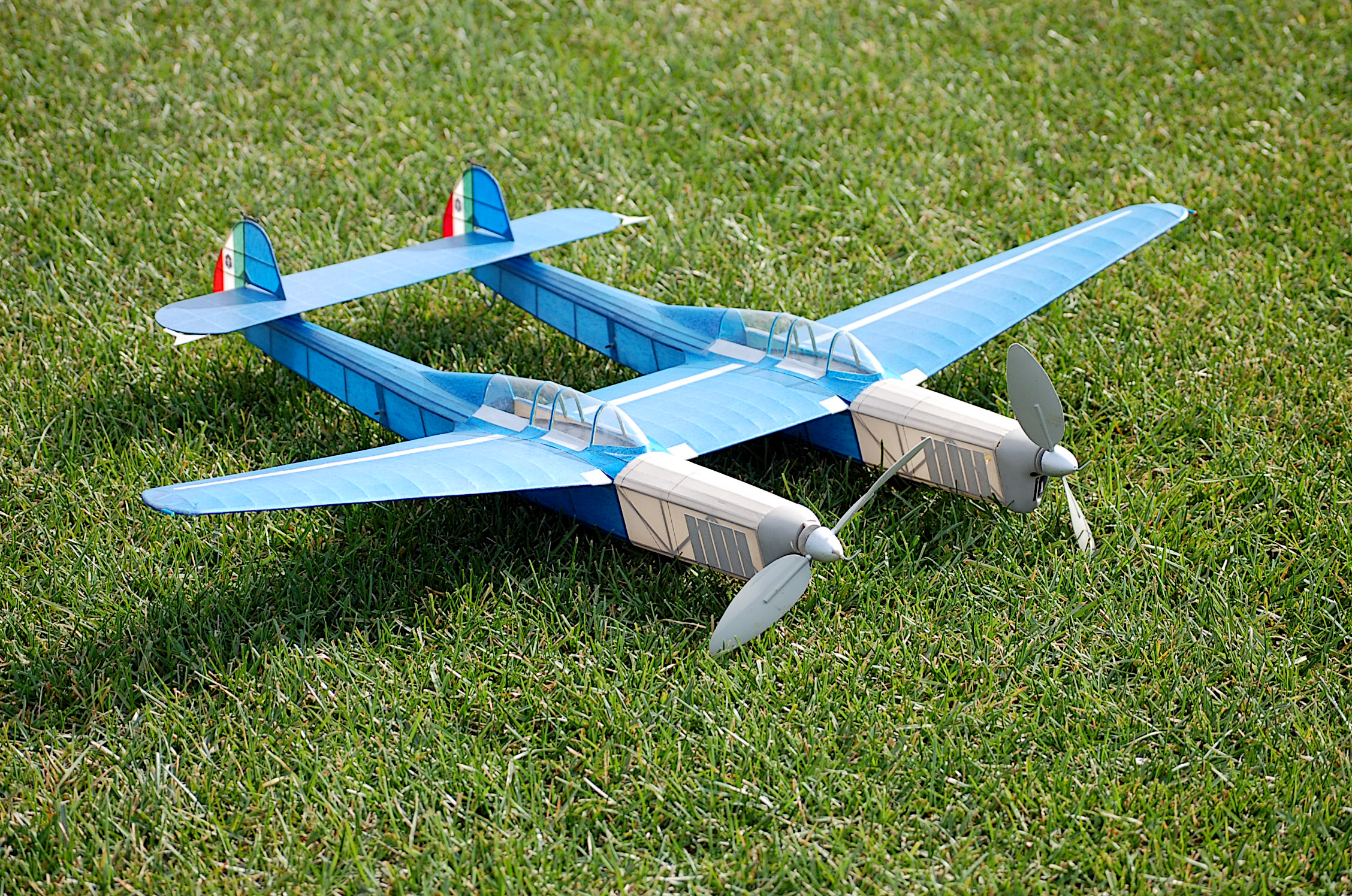
The BN.1, with its excellent proportions and long nose moment, is well-suited to a rubber-powered flying model. The model was created for Flying Aces Club (FAC) Jumbo Scale Competition and has slightly more than a 36-inch span.
The construction techniques should be familiar to most Scale modelers. In some cases, it was necessary to make educated guesses about various protuberances on the full-scale airplane, because documentation was limited. Some of the construction techniques are similar to those of Czech-designed models, particularly the closely spaced sliced wing ribs, which produce a strong, but lightweight, structure. Note that the two fuselages are identical.
Fuselages
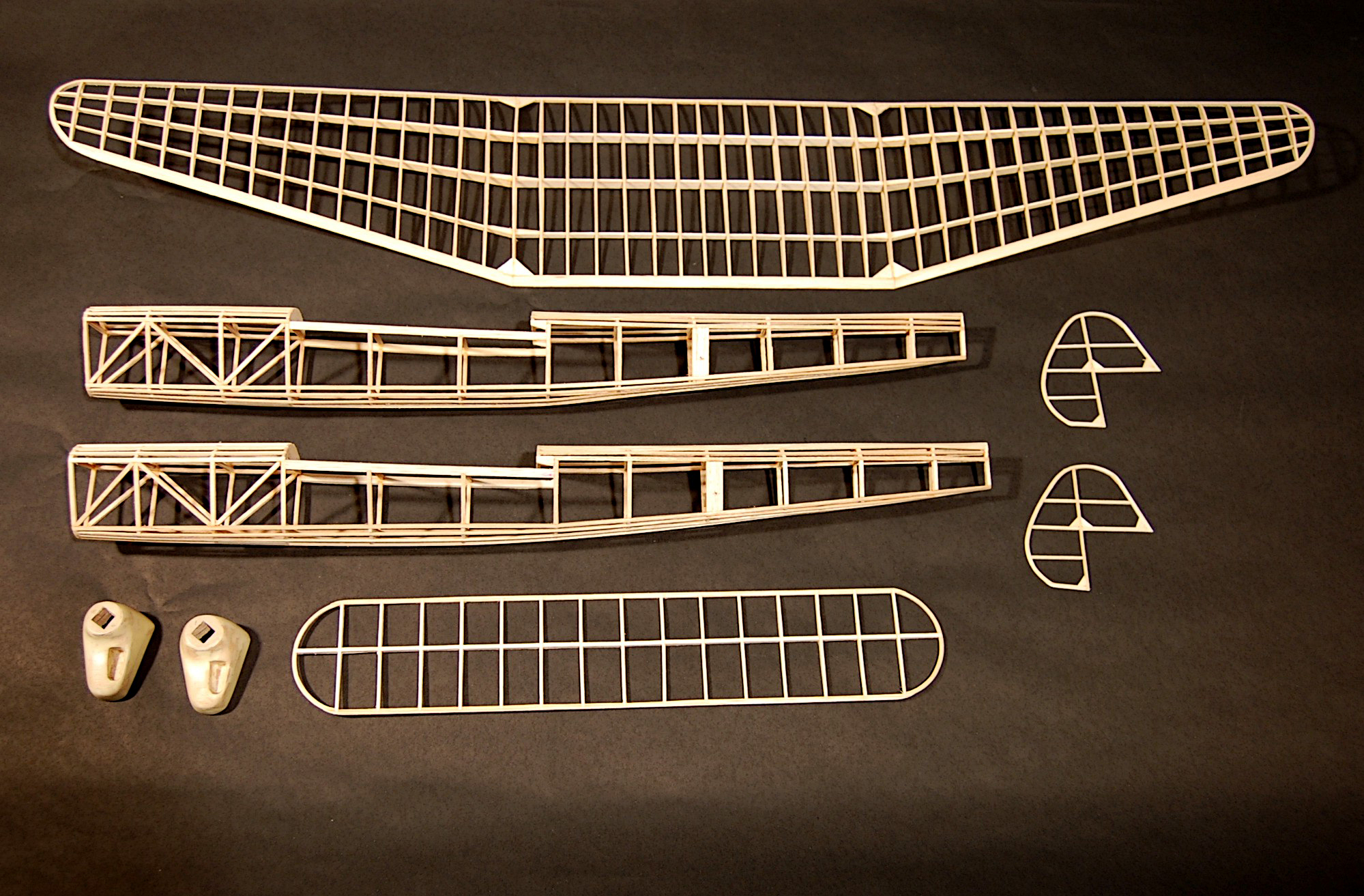
The trapezoidal cross-section of the fuselage eventually tapers to a rectangular one at the tail. The fuselage is flat sided, with stringers only on the rounded formers, top and bottom.
For each fuselage, make two identical side structures of 3/32-inch balsa stock. Build one side and then the other directly on top of the first, separated by plastic kitchen wrap. At this point in construction, the two sides are glued together only at the rearmost tail post.
Add the crossmembers G, F, and E, in that order, starting at the widest part. Refer to the individual cross-section drawings to measure the crossmembers. Once the basic frame has been completed, add the top and bottom formers and lay in the 1/16 square stringers.
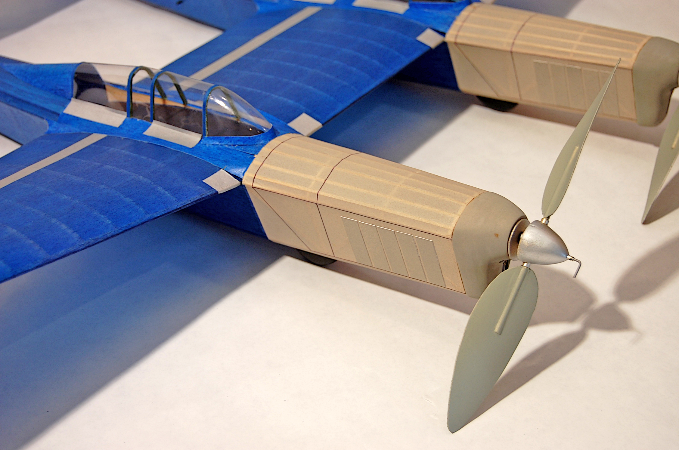
The nose block was cut from a balsa block constructed of cross-laminated 1/8-inch sheets for strength and then hollowed out with a motor tool. The various air intakes on the nose block were either inset with the motor tool or simulated with black tissue after the nose block was painted.
Although the nose block was originally glued directly onto the station A structures, this proved to be impractical because of the narrow opening and high thrustline. Eventually this was converted into a removable nose block arrangement using three pairs of small, rare earth magnets and two alignment strips (see the plans and accompanying photo).
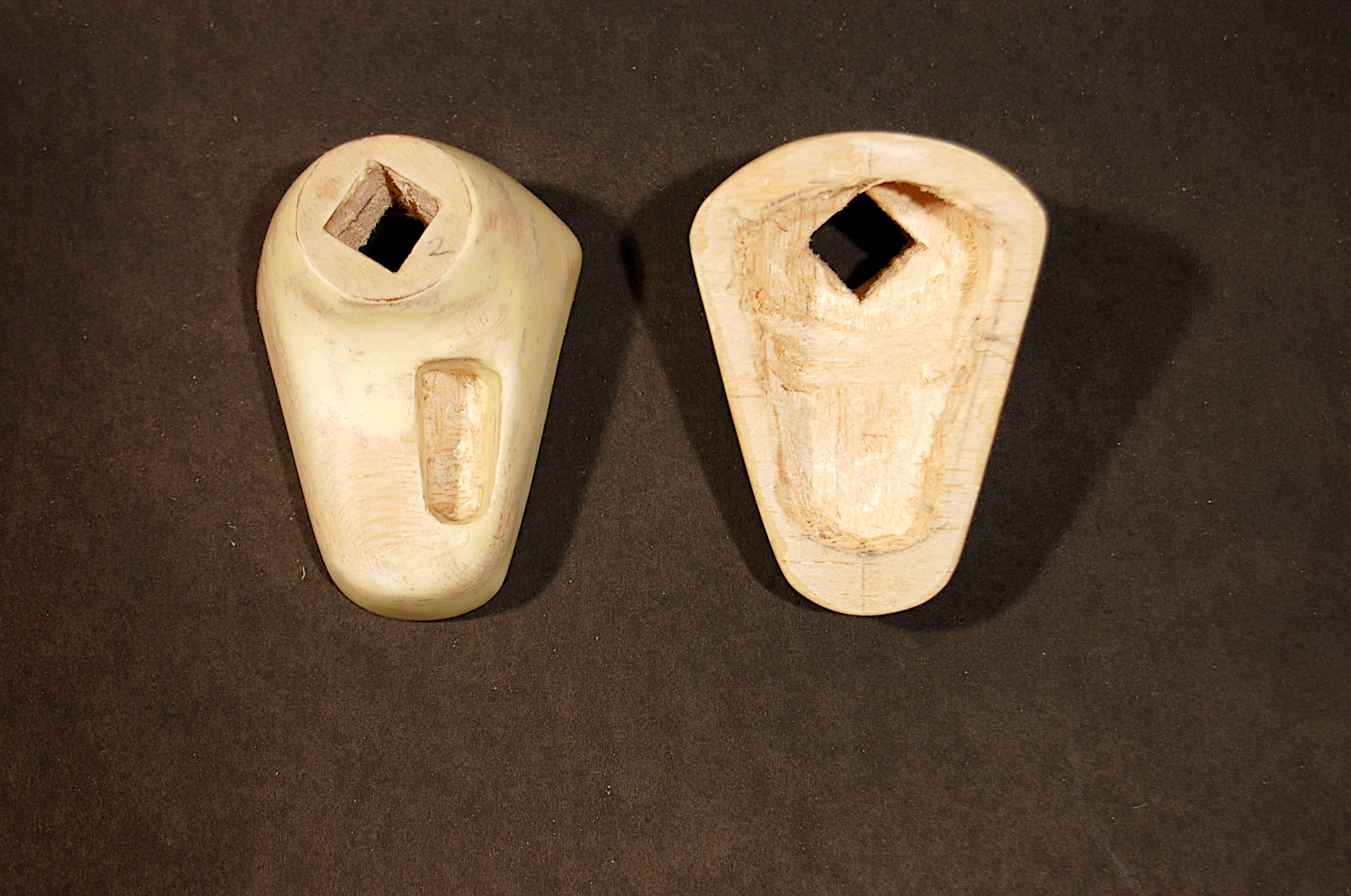
This arrangement is reliable in operation and allows easy access to the rubber motor.
Wing and Tail Surfaces
The wingtips, stabilizer tips, and rudder outline are built up of laminated layers of 1/32 x 1/16-or 1/32 x 1/8-inch balsa. For each laminated structure, draw or photocopy the innermost line of the laminations, then transfer or glue this outline to a piece of heavy card stock and cut along the outline. Coat the cardboard with wax rubbed on from a candle, which will act as a parting agent.
The cardboard is securely pinned to the building board with waxed paper underneath. For each laminated structure you will need three balsa lamination strips. These are steamed for 10 to 15 minutes using an ordinary vegetable steamer within a closed pot, which will make the laminations pliable.
Brush a thinned mixture of white glue, such as 60/40 glue-to-water, between the laminations, and pin them to the form with straight pins. Allow these to dry overnight. A laminated tip can then be removed from the board and carefully trimmed with a sharp hobby knife or razor.
The stabilizer is a combination of straight stock and laminated tips. You may want to add 1/32-inch thick cap strips to both sides of the spar and crossmembers for added strength. The cap strips add little weight and prevent warps.
The vertical tails can be built as shown on the plans and do not require cap strips. The simulated counterweights will be described later. The wing consists of a rectangular center section with tapered outer panels. The dihedral breaks are between these.
Lay down the LEs, TEs, and wingtips, gluing everything together except where the outer panels will join the center section. The sliced rib template, shown on the plans, is glued to a piece of 1/16-inch thick plywood and carefully cut out.
Making sliced ribs is simple: Cut a rectangle of firm 1/16-inch balsa sheet roughly 3 x 6-1/8 inches. The grain must run parallel to the longer dimension, which corresponds to the LE to TE dimension.
Hold the template against the balsa sheet and smoothly cut along the curved outline. Move the template down 1/16 inch and cut again. There’s the rib. Repeat until you’ve manufactured at least 45 ribs. Make a few extra ones, just in case.
With the outline structures pinned in place, glue in 1/16-square sticks against the plans at every rib location. The three spars for the center section are untapered, but the outer section spars are tapered to the dimensions given on the plans.
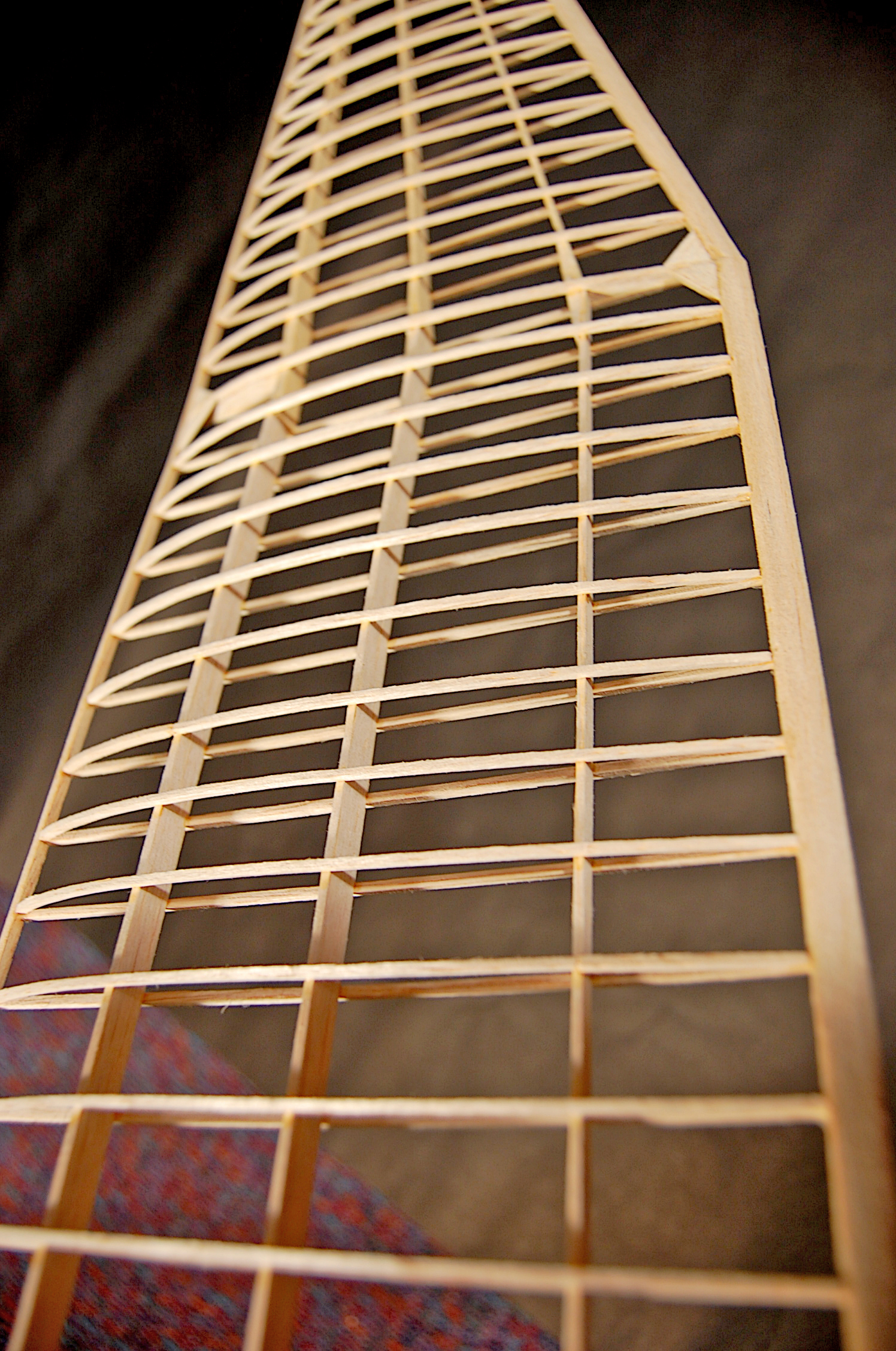
After the 1/16-square lengths are glued into position, glue the spars in place. It is important that these be perfectly upright at right angles to the surface of the building board. Check these frequently with a small right-angle triangle as you glue and pin them into position against the 1/16-square lengths.
Now glue in the curved, sliced top strips. For the moment, leave off the two top strips where the dihedral break occurs. Where the wing tapers, always shorten the sliced top strips by cutting away at the TE of the top strips, never from the LE.
This goes together quickly. When everything has thoroughly dried, leave the center section in place, but remove the tapered outer panels from the building board. Raise the tip of one outer panel 2 inches above the building board and run a long, straight sanding stick across the LEs, TEs, and spars.
Carefully sand in the correct dihedral angle so that the outer panel will properly join with the center section. Repeat this procedure with the other outer wing panel. When the outer panels are raised the requisite 2 inches, they should align perfectly with the edges and spars of the flat center section. They can now be glued into place and curved top strips can be added. It is a good idea to add triangular gussets to reinforce the wing joint.
Covering and Assembly
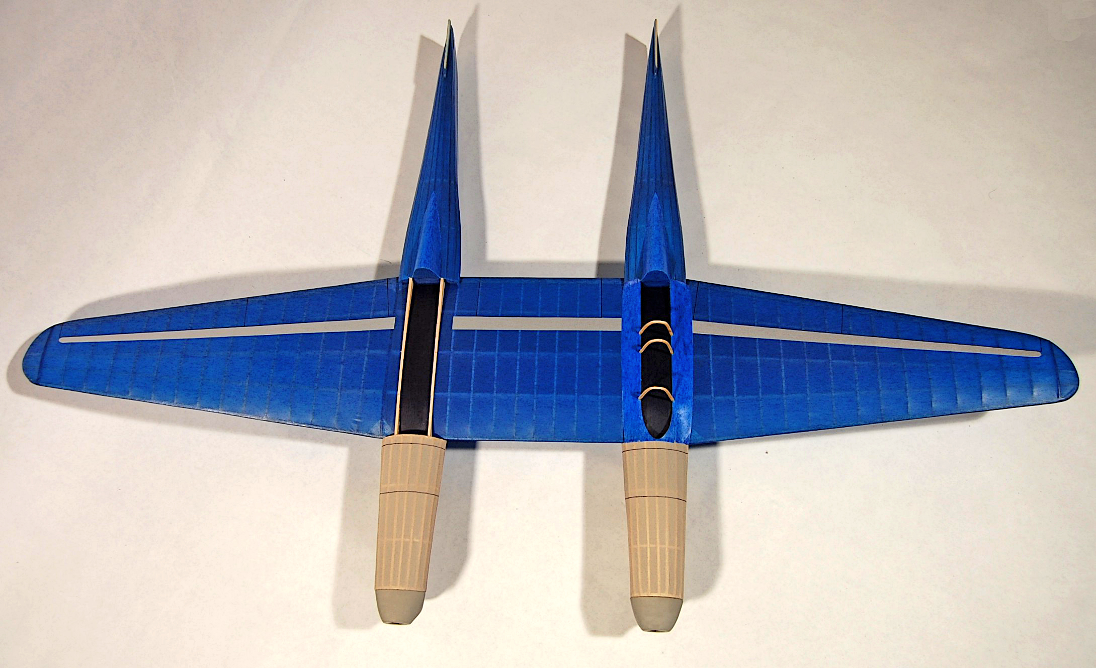
Each of the finished structures is covered with dark blue tissue except for the front of each fuselage (former D forward) and the rudder of the vertical tail surfaces. Shrink the tissue with a mist of rubbing alcohol.
Apply two coats of clear nitrate dope or lacquer. The rudders are left white so that strips of green and red tissue can be doped over them to create the tricolor rudder stripes. A small House of Saxony shield insignia is glued to the outer white stripes.
The white forward fuselage and the nose block should be misted with a coat of light gray dope. If you engrave the engine inlets into the nose blocks, increase the illusion of depth with black paint or tissue inside the inlets.
Photos show no conventional exhaust pipes, but rather an arrangement of five shutters on each side of the engines. Sometimes these appeared open in the photographs and sometimes they were closed. My model simulated closed engine shutters with strips of heavy paper sprayed the same gray color, glued to the tissue as shown on the plans.
Small structures, perhaps counterweights, also appear in drawings and pictures of the airplane and are simulated on the model with black or silver paper cutouts folded over .010 music wire that is carefully inserted into the tail structures and glued in place. The tail skids are made of fine music wire and scrap.
Assembly
Carefully align the fuselages with the wing. Check and double-check that they are in the correct locations and that everything is square. Glue the fuselages in place against the wing. The headrest is made of hollowed balsa or foam, smoothly sanded and painted to match the blue fuselages.
A headrest is glued in place on top of former H. Now the canopies can be added. The cockpit side formers are delicate 1/16-sheet structures that are glued in place atop the wing, flush with the headrest.
Attach black tissue to the top of the wing between the side formers to give the cockpit area greater depth. The canopy frames can be laminated, much as the flying surface tips were, or they can be bent from bamboo.
Glue the three canopy frames in their proper locations along the canopy side formers. Create most of the canopy with thin acetate sheets glued to the canopy frames. Only the front section of the canopy has a compound curve that requires the piece to be plunged or vacuum-formed.
A single main wheel on each fuselage is depicted in the retracted position. I created a single wheel, turned on a drill, from which sections were cut to represent both retracted wheels. It can be made from hollowed balsa or foam and painted flat black before being glued to the fuselage undersides.
Simple wing fillets are made from doped bond paper. To make the nose block removable, the small, powerful magnets must be carefully located and recessed flush with the surfaces to be mated. They can then be glued in position.
The spinners were turned on a drill. You may want to use commercial plastic propellers, but built-up or carved ones are more efficient. The propellers are made to turn in opposite directions (toward the wingtips, viewed from the front) in order to minimize torque effects.
The blades were cut from plastic yogurt containers, affixed to bamboo spars, and then glued into a brass tube. That tube had first been drilled at its center to accept a smaller-diameter brass tube with a simple ramp-type freewheeler filed into it. The tubes were soldered together.
The angle of the spar-and-blade assembly, relative to the cross-tube, was determined with a simple fixture, and then cemented permanently into the cross-tube with instant CA glue. The ramp freewheeler pokes through the end of the spinner. It works well.
Flying
Other than a slight amount of downthrust and nose weight, the model required no additional adjustments. Its first flight was more than a minute! Its second flight—nearly 1-1/2 minutes—was at the 2010 FAC Nationals, which was good enough for second place in the Jumbo Scale event.
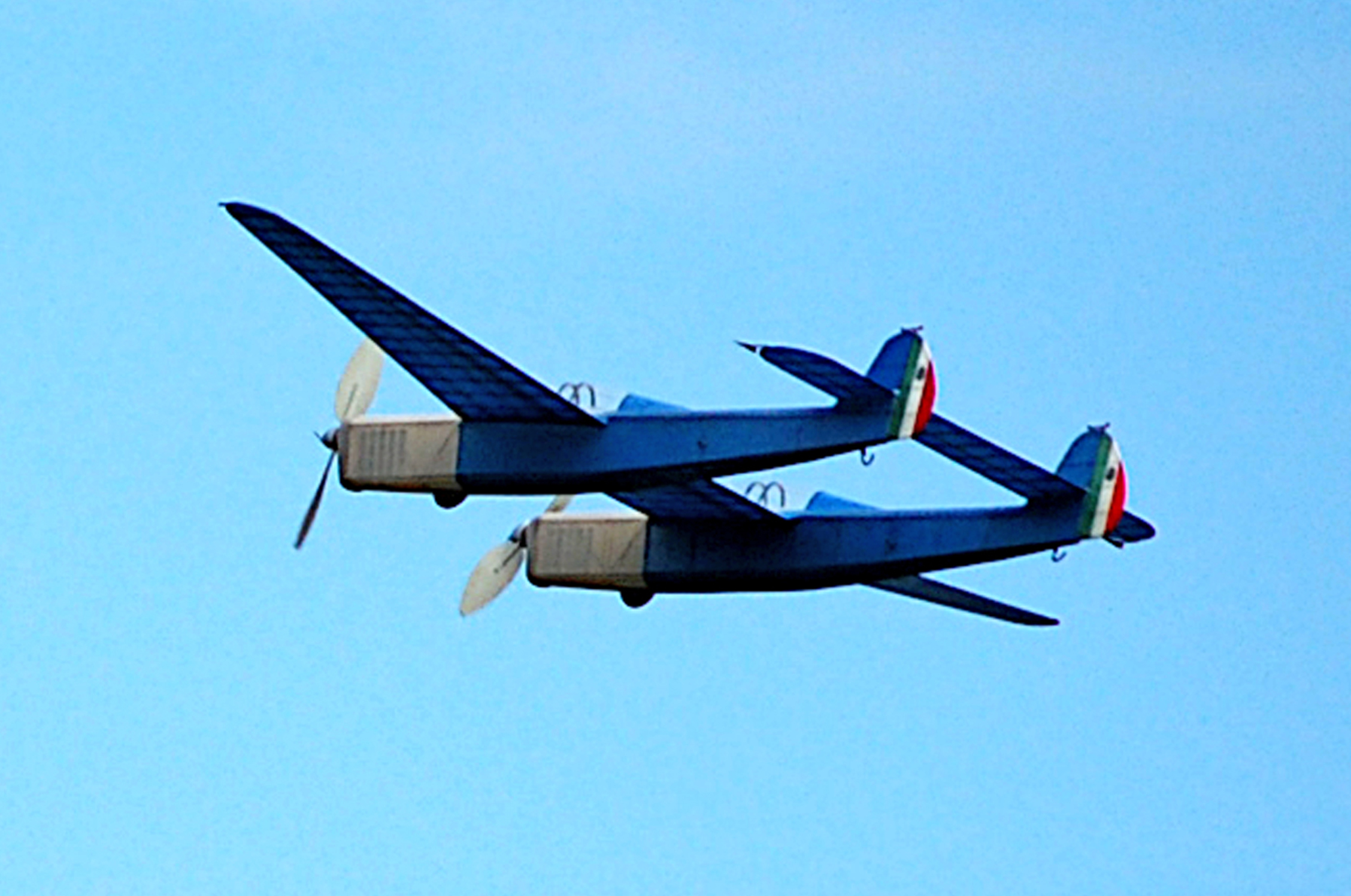
My BN.1 took first place at the Fall Wawayanda, New York, meet. Each motor currently consists of two 28-inch loops of 1/8-inch FAI Super Sport rubber, but a more robust motor of three loops of 3/32 is planned for next flying season. The weight of the airframe, without rubber, is 75 grams.
SOURCES:
AMA Nats
https://nats.modelaircraft.org/
AMA Plans Service
(765) 287-1256, ext. 507
https://plans.modelaircraft.org
Bestetti-Nardi BN.1 Plans
Plans No. 1064
https://plans.modelaircraft.org/product/bestetti-nardi/


Comments
Add new comment