Control Line Scale
By Fred Cronenwett | clscale7@gmail.com
As seen in the August 2025 issue of Model Aviation.
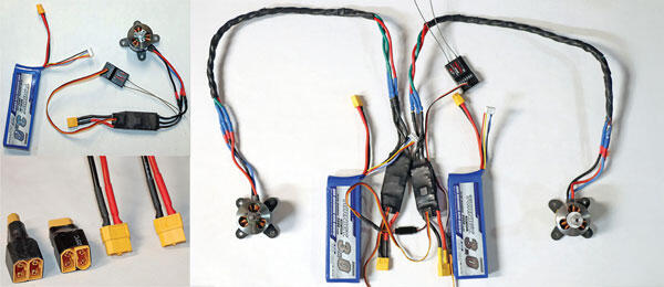
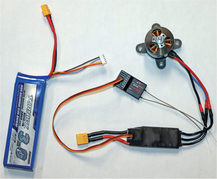
FLYING WITH TWO or more electric motors requires you to pick where all of the parts will be located in the model. A model with one brushless motor also has the ESC, LiPo battery, and the receiver. In some cases, you also might want an arming plug on the model.
The typical 2.4 GHz RC unit and receiver that is available today will easily interface with electric motors and ESCs that are commonly available. When you do buy the ESC, make sure that it can handle the peak amperage that the motor pulls from the battery. If the ESC has a battery eliminator circuit (BEC) feature, you can have the ESC power your receiver.
When it’s time to configure a model with two or more electric motors, you have some choices regarding where to put the ESC and LiPo battery. If you extend the power wires from the LiPo to the ESC, there will be a voltage drop; however, if you extend the three wires from the motor to the ESC, you will have the same control over the motor without any problems.
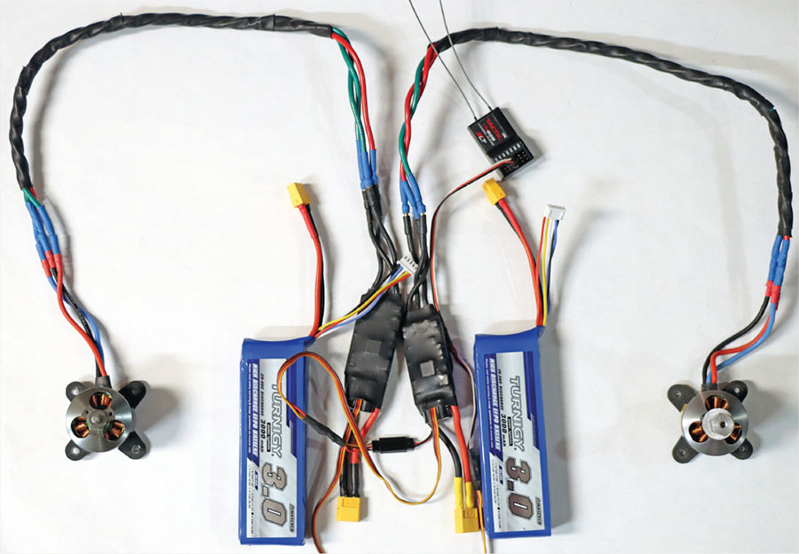
You only need one receiver, regardless of how many motors are on the model. The throttle channel will be connected to all of the ESCs on the model using a Y harness, where the signal and ground are common. If you use an ESC with a BEC feature, you don’t want the other ESCs feeding power to the receiver at the same time. Those ESCs have the red wire cut so that they only get the signal and ground. I put a short servo extension between the Y harness and the ESCs that don’t feed power to the receiver and have the red power wire cut.
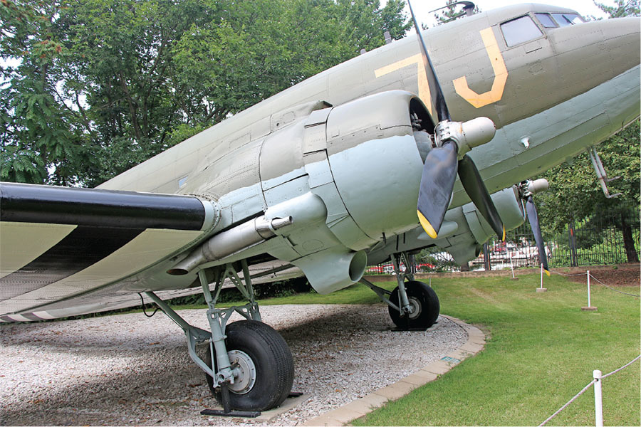
Let’s use the Douglas DC-3 as an example. The full-scale aircraft has very small cowlings and nacelles, which does not leave much room for the ESC or the battery, especially if you have retractable landing gear. The idea is to put the receiver, LiPos, and the ESCs in the fuselage. The cowling would contain the motor, and the three motor wires would be extended to run into the fuselage.
If you are building a trimotor or a four-engine model, the same principles can be used to determine where the ESCs, battery, and receiver will be located. Make sure that you can replace the motor, wire bundles, servo extensions, batteries, ESCs, and the arming plug for any future repairs.
The LiPo Battery
For this example, each motor requires a 4S 2,000 mAh LiPo battery to fly a complete flight. The easiest way to arrange the parts is to have two separate batteries—one for each motor. If you do that, each motor behaves like a single motor setup. The only item that both motor ESCs would share is the connection to the receiver through a Y harness.
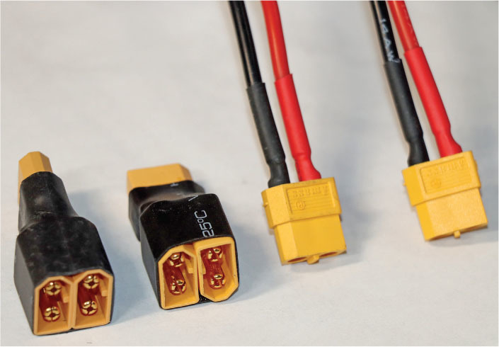
There are two special connectors that you can get for LiPo batteries that can be helpful in certain situations. The first will take two batteries and put them in series, or, in other words, add the two voltages together. This connector will take two 4S batteries and create the combined voltage of an 8S battery. I have 3S, 4S, and 5S batteries in my shop, so when I need a 6S battery to power one of the models I fly, I use this connector.
The second connector will take two 4S batteries, each with 2,000 mAh, and will create the combined voltage of a 4S battery, but the overall mAh is now 4,000. This is helpful if you don’t have a larger battery but have two smaller ones available. Plugging the two batteries into this connector will double the capacity of the combined pack but retain the voltage of the individual battery. Decide where you want the battery to be located in the model so that you have easy access at the flying site to remove and replace it.
Extending the Motor Wires
If you are building a twin-engine model and there is no room in the nacelle for the battery and the ESC, you have to extend the motor wires that plug into the ESC. These are three wires that come from the ESC with the bullet connectors that connect to the motor.
I like to keep the bullet connectors on the existing ESC and motor as-is. I then create a wire bundle with bullet connectors on both ends that plugs into the motor and the ESC and route that through the wing into the nacelle so that I can plug the ESC into the end that is inside the fuselage and the motor into the other end.
You can also buy motor extenders with bullet connectors attached and ready to use or you can make your own. You should also consider servo extensions and battery connectors that allow you to double the mAh of two LiPo batteries or put them in series.
Electrical Resources
It’s difficult to tell by just looking at an electric motor how much power it has, what size of propeller it is designed to turn, and what ESC should be used. eCalc is an online software program that determines the motor data that can predict the performance of the model that you are looking at building. With the right data, such as the wing area, wingspan, weight, etc., you can establish whether a motor is going to be too small or large for your project.
The Innov8tive Designs website has lots of propeller charts for the Cobra and BadAss brushless motors that the company sells. The charts tell you what power and propeller sizes should be used to determine whether a particular motor will suit your needs.
2025 Contest Season
The Lafayette Esquadrille’s Broken Arrow CL Stunt & Scale Contest has joined forces with the National Association for Scale Aeromodelers (NASA) Scale Classic for 2025. These two contests were combined into one to avoid conflicts between all of the Scale contests that are held in September.
Contest Calendar
- Midwest Regional C/L Championships: August 30-31, Aurora, Illinois
- Broken Arrow CL Stunt & Scale Contest: September 20-21, Buder Park, Valley Park, Missouri
Land softly!
SOURCES:
NASA
Motion RC
(224) 633-9090
Innov8tive Designs
(442) 515-0745
eCalc


Comments
Add new comment