
Installing gear
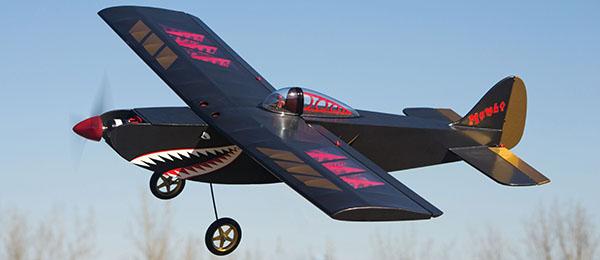
At A Glance
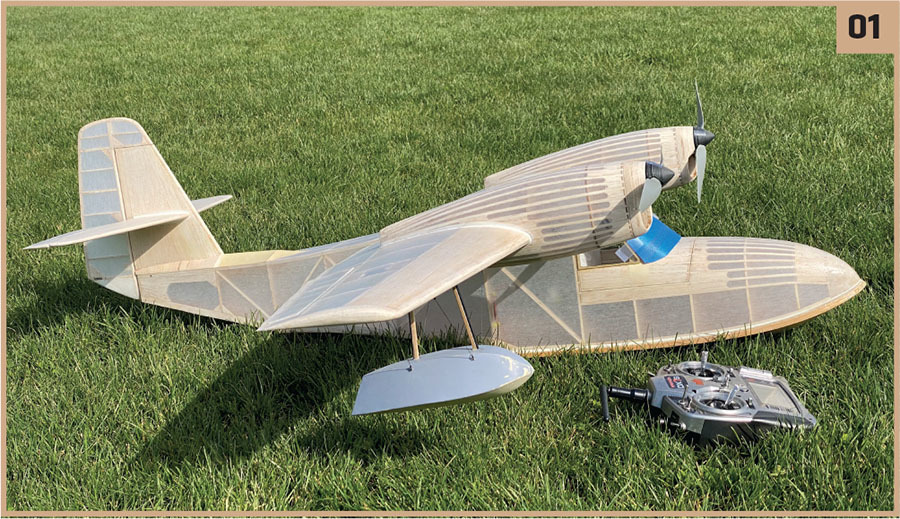
Specifications
Wingspan: 60 inches
Length: 46.6 inches
Wing area: 558 sq. in.
Flying weight: 56 ounces
Power: 2315-880 Kv motors; 3S 3,300 mAh LiPo battery; two 10 × 7 propellers
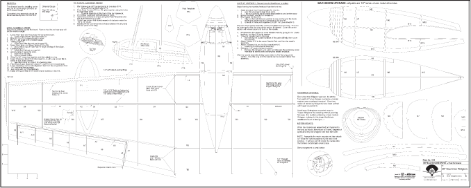
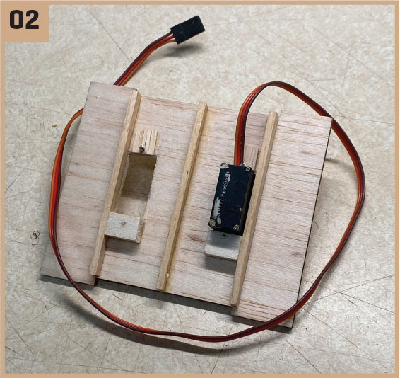
PURCHASE PLANS
DOWNLOAD FREE PLANS!
Full Plans
Tiled Plans
Welcome back to the second installment of the Infield Engineering Grumman Widgeon build! Last month, I completed all of the basic woodwork for the airframe. Now I’ll shift the focus to installing the internal equipment and knocking out some tasks in preparation for the covering.
Before I launch, however, I should mention an important step that applies to all wooden waterplanes.
Water will eventually find its way into the structure. This is especially true of the fuselage because it has the most direct contact with water, as well as a number of openings for various purposes. It is highly advisable to seal the wood before installing electronics, movable controls, or plastic parts.
For my Widgeon, I diluted Deft lacquer with lacquer thinner and shot all of the wood assemblies and parts with a spray gun. There are other products that will work as well, but this is the rare case where I avoided water-based products because the goal was to keep the wood from warping after getting wet.
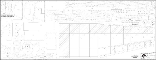
Servo Tray
Installing the servo tray is a good place to get started. Begin by cutting holes for the rudder and elevator servos in part ST1. Glue in a little balsa scrap below the servo ears to give the servo screws something to bite into. I added some scrap balsa strip to reduce flexing of the tray while I was at it.
Once the servos are secure, glue the back of ST1 to fuselage former F8. Complete the servo tray installation by gluing part ST2 to the front of ST1 and to the insides of wing saddles K7.
Tail Group Controls—Fin and Rudder
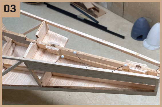
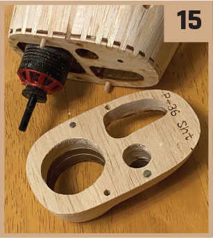
To mount the tail fin, install short locating pins into the underside of the fin using the holes in part V2. The pins can be made from 1/8-inch dowel or 3mm carbon-fiber tube. They should extend 3mm below the underside of the fin assembly.
Reinforce the sides of fuselage keel K2 to form the pin holes. When fitted properly, the lower front corner of the tail fin will fit in the notch formed by former F11 and K2, and the pins will drop into the holes in K2. Forming a box with scrap wood around the front pin hole, as shown in the photos, will make this area much more rigid.
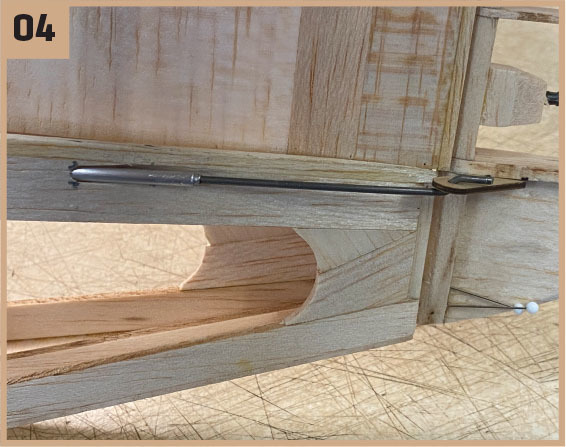
The rudder can now be fitted. For my prototype, I used 1/8-inch Robart Hinge Points for all of the control surfaces. As always, builders can substitute their favorite solutions. A conventional control rod was fabricated from aluminum tubing with music wire fittings epoxied into each end of the tube.
The Elevators
Because the horizontal stabilizer is mounted high on the fin, rigging the elevators takes a little more thought. A straight control rod from the main servo tray isn’t an option because most of the rod would be sticking out of the fuselage.
My friend, Tim Cullen, built the first prototype of this design. Tim solved the problem by installing the elevator servo in the tail fin. This worked great because it resulted in a short control rod that fit neatly under the stabilizer. The Widgeon has a long enough battery tray to offset the small addition of tail weight.
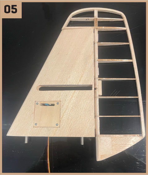
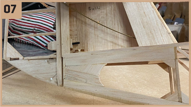
For my Widgeon, I opted to use a Sullivan Products cable running from the stock servo tray through the fuselage and exiting through the side of the fin. I’d argue that Tim’s way is simpler, but I had all of the parts for the cable in hand, so I went with it.
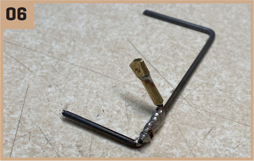
Either way, the two elevators need to be connected together. This can be done by bending music wire to form a C-shaped joiner. A control arm can be added directly to the joiner. I did this by silver-soldering another bit of music wire to the joiner and capping that with some brass tubing to form the tang.
Sullivan cables work great when they are installed properly but only with a single bend of a large radius. They also need to be held in place with hangers at each former to keep them from flexing. Making the cable run smoothly before it is locked into position is time well spent. Leaving the backside of the fin without sheeting, as discussed last time, allows for plenty of test-fitting and adjusting.
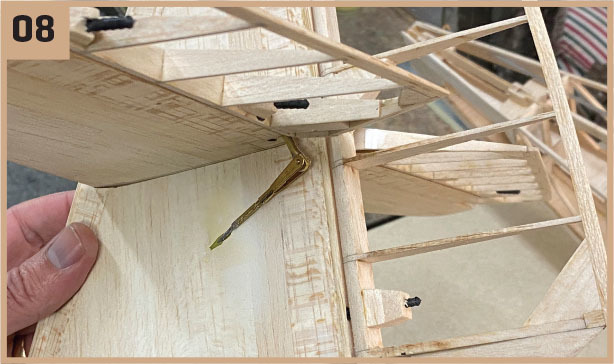
Once the optimum cable path is identified, epoxy the cable sheath into position. Trim the end of the sheath flush where it exits the fin. The Sullivan cable kit that I used had a nice clevis that was soldered on to connect to the elevator control arm. After trimming the cable to length, another fitting from the kit was soldered to the other end of the cable, which ended in a smooth rod to be connected to the elevator servo with a Du-Bro EZ connector.
The Ailerons
The Widgeon plans suggest a location for the installation of individual servos to operate each aileron. There are other options available to the builder, but here is what was used on my prototype.
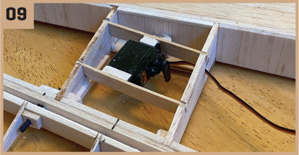
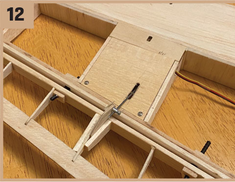
To begin with, rails were fitted to run between the two wing ribs in the identified bay. The rails were positioned for the aileron servo to fit snugly between them when angled so that it is perpendicular to the parting line of the aileron.
Scrap balsa blocks were attached to the rails underneath the servo’s mounting ears. Once I was happy with the fit of the servo, I used silicone caulk to hold it in place. The silicone will hold up to water and is easy to release if a servo must be removed later. Because of the tight fit in the bay, screws weren’t a great option.
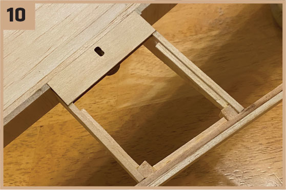
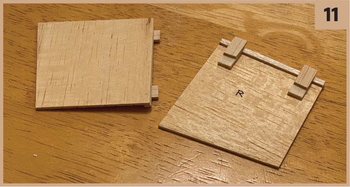
Next, a box was framed into the bay behind the wing float mounting pads. Scrap wood was used to build a recessed sill that would seat a balsa door. The back corners of the sill were made from harder balsa blocks that could be drilled and tapped for screws.
Scrap sheet balsa was cut to fit the bays to form the aileron doors. Once fitted, a front stiffening rail and a pair of tabs were attached to each door. The tabs slipped under the rear float mounting pad to hold the front of the door in place.
Leftover servo screws were used to hold the rear of each door closed. Holes were drilled through the doors and into the corner sill blocks. The holes in the blocks were then tapped with the screws themselves. After removing the screws, a drop of CA into each hole hardened the threads in the balsa blocks.
From there, attaching the servo to the aileron was routine. A short music wire control rod with a Z-bend was connected to the servo arm. The other end of the rod was slid into an EZ connector fitted into a plywood horn. A little 1/2-ounce fiberglass will make the plywood horn durable in wet conditions.
The Cowlings
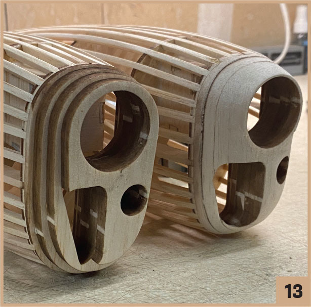
Last month, I stacked up a pile of thick balsa parts to rough out the front of the engine cowlings. The nose block and the noses of the wing floats were created similarly. Now is a good time to finish these parts.
Using the cowlings as an example, begin by sanding the corners off of the parts in the stack. Start with 60-grit sandpaper and sand until the bottom edges of each part in the stack barely show, similar to a set of contour lines on a map. Once you are happy with the general shape of the cowlings, switch to finer sandpaper and fine-tune. I ended with 220-grit sandpaper and just a hint of the contour lines.
After sanding, seal the cowlings. Following fellow builder "Fuzz" St. Martin, I used a mixture of lacquer and baby powder for a combination sealer and filler that sands easily. It smells nice while sanding too.
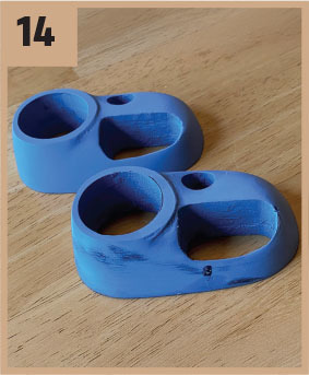
Once the cowlings are sealed, shoot them with high-build automotive primer in a spray can. Using a different color for the first layer will provide a guide to prevent sanding through the primer. Wet-sand with 400-grit then 600-grit sandpaper and the cowlings should be ready for paint. If not, shoot another layer of primer and try again. Finish the cowlings by adding locating pins in the nacelles and pairs of rare earth magnets to snap the cowling fronts into place.
Spinners
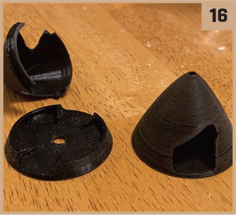
Throughout the years, Widgeons have worn a variety of different spinner types. For my prototype, I went with the short, conical spinner found in photos of factory-fresh aircraft of the 1940s.
A two-piece, snap-fit spinner was designed in SolidWorks to fit this particular model. The resulting STL files can be found on Thingiverse and downloaded for free. I don’t have a 3D printer of my own, but it’s not difficult to find a buddy who does these days. A friend from work was happy to print a pair for my Widgeon.
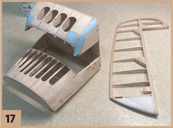
Foam!
There’s a running joke amongst some builders that separates those who build with foam from those who build with wood. Joking aside, having a foot in each camp is handy because both materials are immensely useful.
For this build, a little foam was snuck in as filler to round out the corners of the crew cabin and the bottom of the rudder. Oversized foam blocks were fitted then glued into place with Gorilla Glue. Once cured, the foam was sanded with 60-grit sandpaper until it blended smoothly into the wood framework. Be careful with the sealing iron in these areas! It is possible to melt the foam if the iron is held on it too long.
Fiberglass
Although not a requirement, it is highly recommended that the main hull get a layer or two of fiberglass. As anyone who has waterskied knows, water can be a remarkably hard surface. While the supplies are out, it’s not a bad idea to hit the wingtip floats and the plywood control horns if you are using any of those.
The prototype Widgeon got two layers of 3/4-ounce fiberglass on the front and midsections of the hull. Biasing the second layer by rotating the weave 45° makes the combined fiberglass layer stronger.
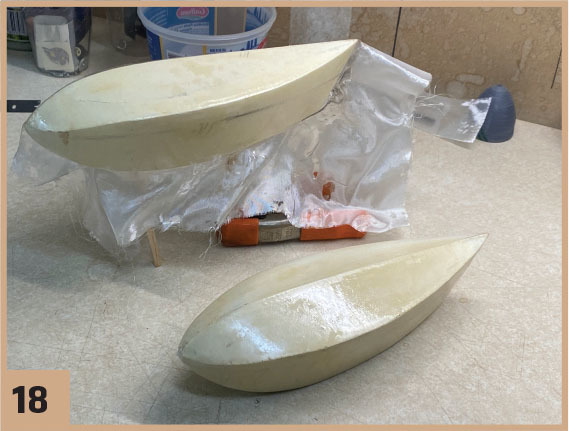
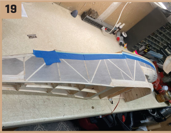
Two layers of thick masking tape were run along the sides of the fuselage so that the fiberglass could be cut cleanly along those lines once the resin was cured. After loosening the fiberglass over the tape, a fresh razor blade was slid over the tape to trim the excess fiberglass cleanly against the fuselage.
Until Next Time!
Again, we covered a lot of ground! At this point, it’s time to start thinking about what covering to use and looking forward to final assembly. Next month, I’ll tackle those subjects and get the Widgeon into the air.
Until then, I hope the building season is keeping you busy!
SOURCES:
Manzano Laser Works
60″ Grumman G-44 Widgeon
RCGroups
www.rcgroups.com/forums/showthread.php?4617725-60-Grumman-G-44-Widgeon


Comments
Add new comment