
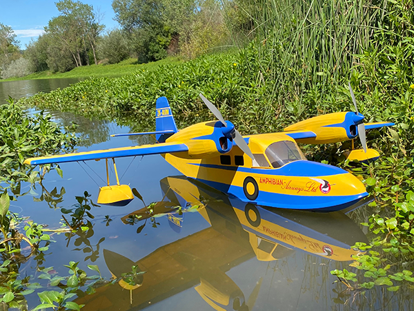
Thanks for coming back for the home stretch of the Widgeon build. Last time, nearly all of the woodwork was done, but I did miss one thing that is needed before the covering can get put on. Let’s knock that out, and then we can put this bird together and get it into the air.
Installing the Windows and Windscreen
The glazing on the Widgeon includes the two cockpit side windows and the front windscreen. The side windows are simple to deal with—just glue the plywood frames to a flat plastic sheet, and then trim the plastic neatly at the outside edges of the frames. For my Widgeon, I used plastic from a large salad container.
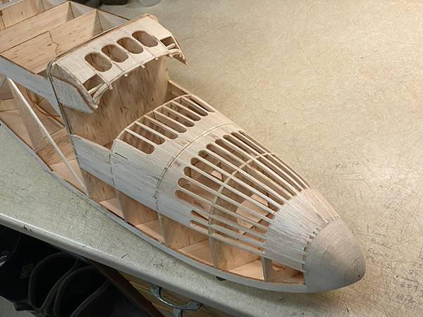
Now prepare the opening for the windscreen. Start by adding some infill to the hatch assembly. Fill in the gaps between the stringers below where the side windows meet the hatch and above and below where the edges of the windscreen will attach. Use soft balsa to fill these areas, and then sand the hatch smooth.
Prepare the upper edge of the windscreen opening. Taping the side windows into place will help keep the hatch assembly square during this process. Use the template included with the plans to cut a windscreen from a plastic sheet.
The front tips of cabin formers C1 through C5 are notched to hold the top of the windscreen in place. Use the windscreen to guide the shaping of the opening formed by the infill so that it makes a smooth curve for the windscreen to mate to.
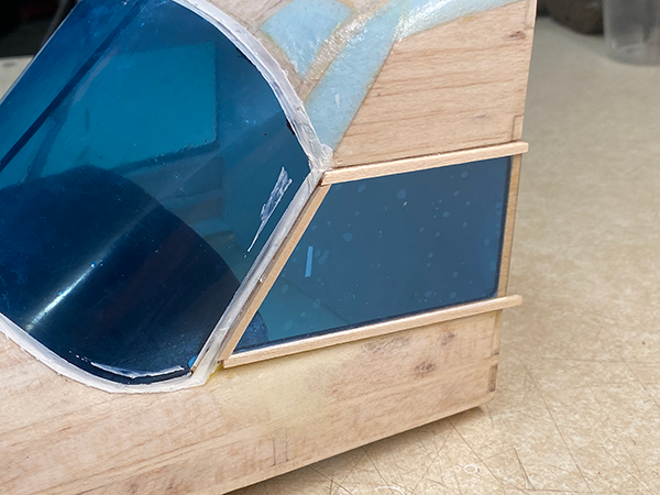
Once you are happy with the fit of the windscreen, the hatch can be covered. Paint the dash and the cockpit interior, and then glue the windows in place. I masked my windows before gluing them in to prevent getting glue on the open areas. I also masked a band around the windscreen and used some filler to seal any gaps and to replicate the windscreen seal.
At Last: Time for Covering!
When I built the Goose prototype in 2012, I used MonoKote for covering and haven’t had any regrets. Plastic film coverings are a natural fit for waterplanes. Just make sure that any seams are tight so that waterproofing isn’t a problem.
More recently, Polyspan has become my go-to covering. I like that Polyspan is very easy to paint and that it stays taut better than plastic films. However, Polyspan is not composed of a polyester film but rather an open weave of unoriented strands of polyester fiber. I questioned whether the open weave could be sealed well enough to become watertight.
Fortunately, my friend Shane McMillan, who is in Australia, answered that question for me. Shane built two Polyspan-covered Goose models. After sealing and painting them, he had no issues with leakage. Armed with this information, I forged on with Polyspan. The covering and painting processes that I use have been covered in previous articles—see the "Sources" section. The point here is that you should feel comfortable using the covering material that you prefer.
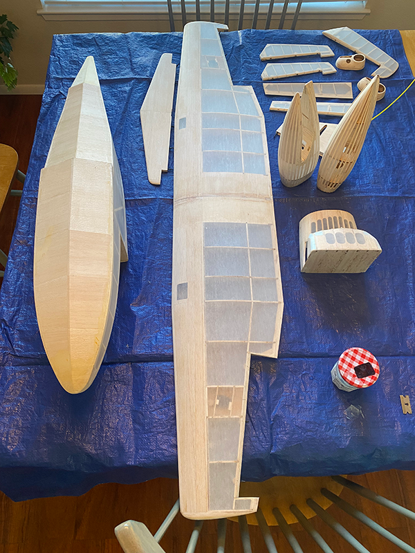
Assembling the Widgeon
Now that the covering is behind us, it’s time to work toward reducing the parts count to four: the fuselage, the wing, and two wing bolts. With that in mind, now is a good time to complete the wing attachment.
Start by making sure that the wing is true to the fuselage. If it is not, draw-sand the wing saddle by slipping sandpaper between the wing and saddle and pulling gently. Work carefully to reduce the tight spots on the side where the wing is high.
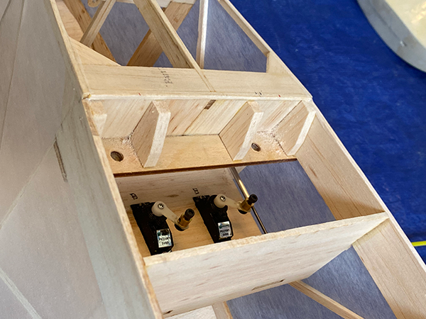
Once happy with the fit, install the screws that attach the wing to the fuselage. I used 1/4-inch x 20 nylon countersunk screws that were recessed into the upper wing on the prototype. Nylon nuts were epoxied to the underside of the wing-bolt boss (WB).
Because there is a gap between the wing and the WB, it’s a good idea to support the underside of the wing from compression forces when the screws are tightened down. I added columns from soft balsa for this purpose. The columns also stiffen the WB and reinforce the intersection between the WB, former F8, and the wing saddle. Additional blocks under the wing at the trailing edge guide the screws into the WB and prevent the wing from slipping sideways or backward. It’s always good for one element to provide multiple functions.
Wiring the Nacelle
Because the wing center section is straight, at first blush, it seemed like mounting the nacelles would be easy. It would have been if it weren’t for the early-style Widgeon nacelles being small and that a lot of wire needed to be fished through them.
There is more than one way to skin this cat, but here is what I found worked well. Cut a large hole in the upper wing skin that matches the hole in nacelle pad N11. Fish your battery and control wiring for the ESC from the wing root into the bay that you have just opened. Make sure that you have enough wire to pull forward through the front of the nacelle without pulling the tag end past the wing root.
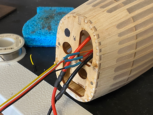
Tie the ends of the battery and control wires together with string. Tie a magnet onto the other end of the string, leaving several inches between the magnet and the ends of the wiring. Coil this neatly in the wing bay. With the wiring stowed, the nacelles can be attached for good.
Spend some time getting the fit right. The two front faces of the nacelles should be parallel to one another. Once the fit is locked down, put some low-tack tape on the wing to capture the outline of the nacelles. Slide the nacelles away, add the adhesive of your choice, and slide the nacelles back. Use the tape to restore the nacelles to their previous positions and to keep the adhesive from smearing onto the wing.
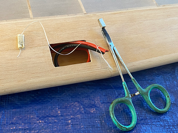
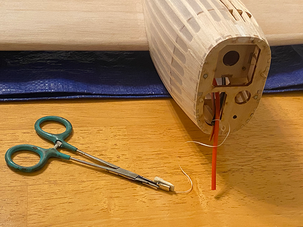
Now back to the ESC wiring. I clamped a second magnet in a pair of forceps. I was able to catch the first magnet that had been stashed in the wing bay by fishing the forceps through the front of the nacelle. After carefully pulling the forceps back, the string, and then the wiring, were extracted from the nacelle.
After exposing the battery and control wiring, it was soldered to the ESC. Once it cooled and was tested, the ESC was tucked into the nacelle and the excess wiring was pulled back through the wing root. By the way, you could use long extensions with plugs for the control wires if soldering isn’t your bag.
Power for the Widgeon
While searching online for motor options for my prototype, I reviewed the offerings at Innov8tive Designs. I really liked the data tables and CAD files that were included with each motor that was offered. At the bottom of the webpage, it said, "We answer the phone!" CEO Lucien Miller answered the phone on the second ring.
After listening to the details of my build and my flying goals, Lucien narrowed the search down to the BadAss 2315 family of motors. He recommended the 1,100 Kv model on a 4S battery as the best option for the power and weight for this application. Being a bit of a contrarian, I went with his second choice, the 880 Kv version, which would allow me to run a Scale 10-inch propeller on either 3S or 4S but with higher power consumption on 4S than the 1,100 Kv motor.
I placed an order for a pair of motors, ESCs, silicone wiring, and servo extensions. I couldn’t have been happier with the results.
Adding the Tail Fairing
The tail end of the full-scale Widgeon is remarkably angular. The sides and top of the fuselage are flat panels. In addition, a sheet-metal fairing was installed in front of the fin.
I replicated the fairing with a combination of card stock and thin balsa. Start by gluing the last fuselage parts F10T and F11T on top of their respective formers.
Card stock was fitted to span between F10T and F11T and to create an apex in front of F10T. I used hard 1/16-inch cross-grained balsa strips for the back part of the fairing. Card stock would work too, but the wood helped stiffen the fin mounting. After a bit of trimming and sanding, the fairing was sealed with water-based polyurethane.
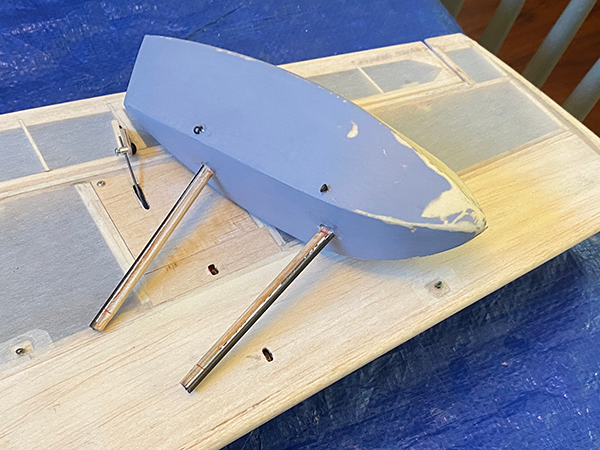
Float Attachment
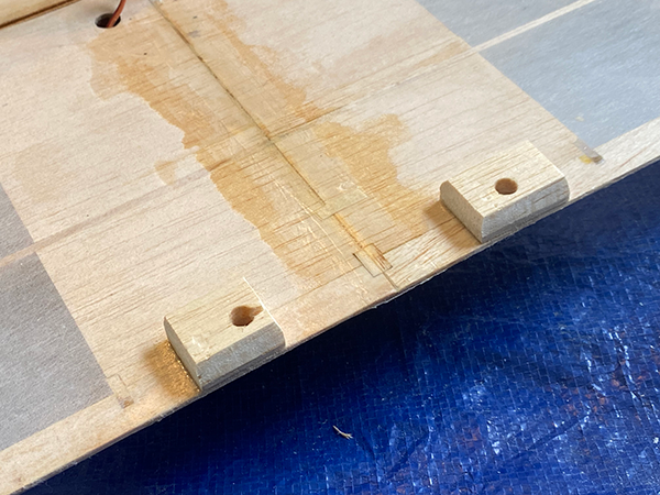
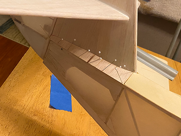
Adding bracing wires to the Widgeon’s wing floats will make their attachment much more robust. Drill holes in the rigging blocks in the wing. Drill a second set of holes in the floats themselves. The rigging points in the full-scale Widgeon are at the sides of the floats.
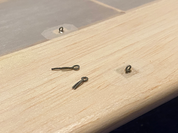
Small cotter pins can be used for the attachments or you can make your own. I twisted .035 wire around a 1/16-inch drill bit to make mine. Epoxy the pins into the holes in the blocks and the floats.
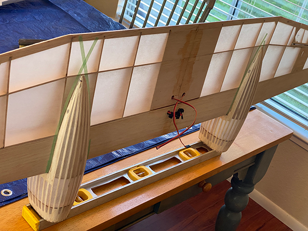
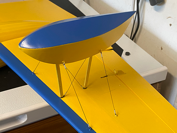
For the float struts, I epoxied 3mm carbon-fiber tube to strips of 1/8-inch hard balsa. After shaping, the struts were epoxied into the floats. Trim the struts to the length shown on the plans. Epoxy the floats into the pockets in the wing.
Once the epoxy has set, add the bracing wires. I used Kevlar fishing line for this job. To simulate the terminal hardware and to help keep my knots snug, I ran the lines through short lengths of 1/16-inch outer-diameter aluminum tubing and pressed these "fittings" against the rigging eyes. A dab of epoxy under each fitting locked each line into place.
Adding the Spray Rail
Most flying boats use a spray rail to divert water from the bow wake out and away from the propellers. I skipped this on my Goose. The Goose comes off of the water fine, but I have always wondered whether it would have been even better had I added one.
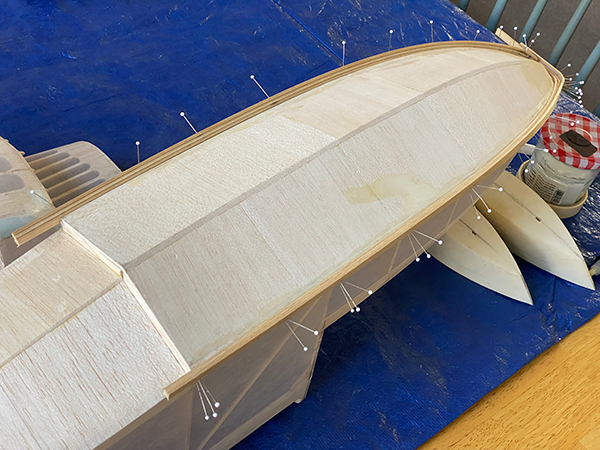
With that said, there was no way that the Widgeon prototype would go without. For my spray rail, I soaked strips of the softest 3/32 balsa I had in water until it softened even more. After covering the edges of the fuselage hull with waxed paper, the first strip was pinned into place. The next two strips were glued on but offset downward.
Where I went wrong was trying to wrap the relatively thick strips around the Widgeon’s nose. Fellow builder "Fuzz" St. Martin again came to the rescue and suggested wrapping the nose separately with vertical-grained balsa. No worries—after a little filler, mine looked fine, but it could have been done more efficiently.
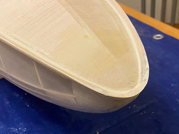
After the rails were completely cured, they were removed and sanded to shape. The spray rails on early Widgeons were made from strips of flashing, but that would be very fragile at 1/8 scale. Although I’ve leaned toward the factory original configuration whenever possible, for the spray rail, I went with a more modern design. This meant a thicker, more-concave cross-section that adds some lift to the hull while diverting water to the sides.
Once happy with the shape, the spray rails were epoxied to the sides of the fuselage. The outer edges of the rail were pretty thin, so these were hardened by rubbing them with CA glue. Finally, gaps between the rails and the fuselage were filled with silicone caulk.
Flying the Widgeon
For the maiden flight, I elected to fly the Widgeon from the grass in a local softball park. Similar to the smaller Goose, the Widgeon scooted along nicely with some back stick. Differential thrust had been programmed into the radio, making control on the ground effective.
Once a little speed was up, the Widgeon lifted off and climbed out. Flying on a 3S 3,300 mAh battery, the weight was 56 ounces, which was a hair more than 100 watts per pound on a full pack. With a low wing loading, this was plenty of power for maneuvering around the softball field.
The water maiden flight was also uneventful. Staying on 3S, the Widgeon rode high in the water and was easily controlled. Again, back stick was the key to keeping the nose up and the wing floats out of the water until the hull began to plane. Once this occurred, the rest of the takeoff runs were predictable.
The 3S battery was more than enough to get airborne and do the basic maneuvers you would expect from a Widgeon, plus basic loops and rolls. Ten-minute flights were no problem. I haven’t bumped it up to 4S yet, but I can say that the airframe will easily handle more weight.
Model Aviation Executive Editor Jay Smith asked me how the Widgeon flies compared to the smaller Goose. Despite their similarities, the Widgeon just feels much bigger. It’s more stable and has more authority. Even so, it’s still comfortable to fly in a small park like the Goose.
Well, That’s About It!
Thanks to all of the builders out there who have shown interest in the earlier Goose design. It’s really been a thrill to see so many of them finished and flown, with a huge variety of different paint schemes and modifications.
Hopefully, this Widgeon will strike the fancy of a similar crowd that is looking for something a bit bigger but with the same type of construction and flying manners. If that is you, I’d love to see a picture of your Widgeon when you get it done.
SOURCES:
Manzano Laser Works
"Model AviationConstruction Series: Polyspan and Paint"
Model Aviation, October 2015
modelaviation.s3.us-east-2.amazonaws.com/ma-construction-series-8-polyspan-and-paint.pdf
"60" Grumman G-44 Widgeon"
RCGroups
rcgroups.com/forums/showthread.php?4617725-60-Grumman-G-44-Widgeon


Comments
Add new comment