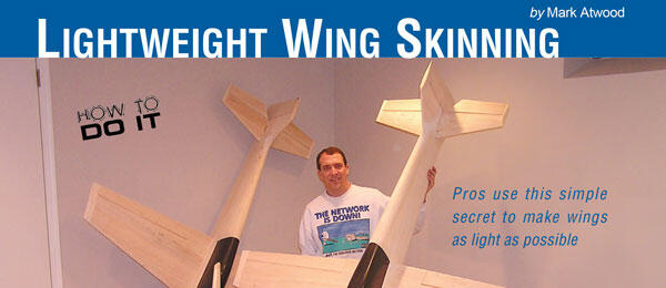
Pros use this simple secret to make wings as light as possible
By Mark Atwood, with sidebar by Jim Hiller
Photos by the author
As seen in the July 2008 Model Aviation.
This article will cover the process of bonding the wing skin to the foam. It assumes that you have already equipped the wing (with servo trays, spars, retract plates, etc.) and made and prepared the balsa wing skins.
The main goals to achieve when sheeting a wing (or stabilizer or surface) are to make it straight, light, and strong. Strength in most cases comes from the shape and structure of the materials you use.
With the possible exception of Pylon racers, which endure very high loads, most wings need little more than a small single spar or, for a two-piece wing, a well-secured wing tube. The phenolic type is sufficient to meet the strength requirements of the aircraft, which in this article is a 2-meter F3A RC Aerobatics (Pattern) model. Given that, the main focus needs to be on light and straight.
Some builders labor intensively to core out foam material. They do this not to save the weight of the foam (which weighs practically nothing), but to remove material where glue would have to be located. The process is time-consuming, and if done improperly it can critically reduce the structure’s stress-handling ability.
If the builder has properly selected the wood materials and the foam cores are made from the lightest material possible (.75-1 pound in density), this method can be used to obtain the lightest structure possible.
The weight of the glue is the enemy when building this light. The following is a simple, low-tech, and low-skill method for producing an extremely light, straight wing, with a minimal amount of glue and fuss. In addition, this construction method is fast because you won’t have to labor over hollowing out delicate wing cores.
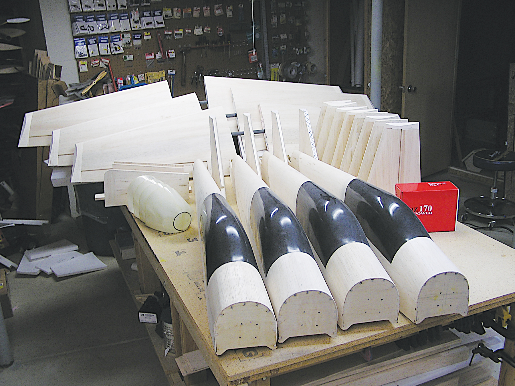
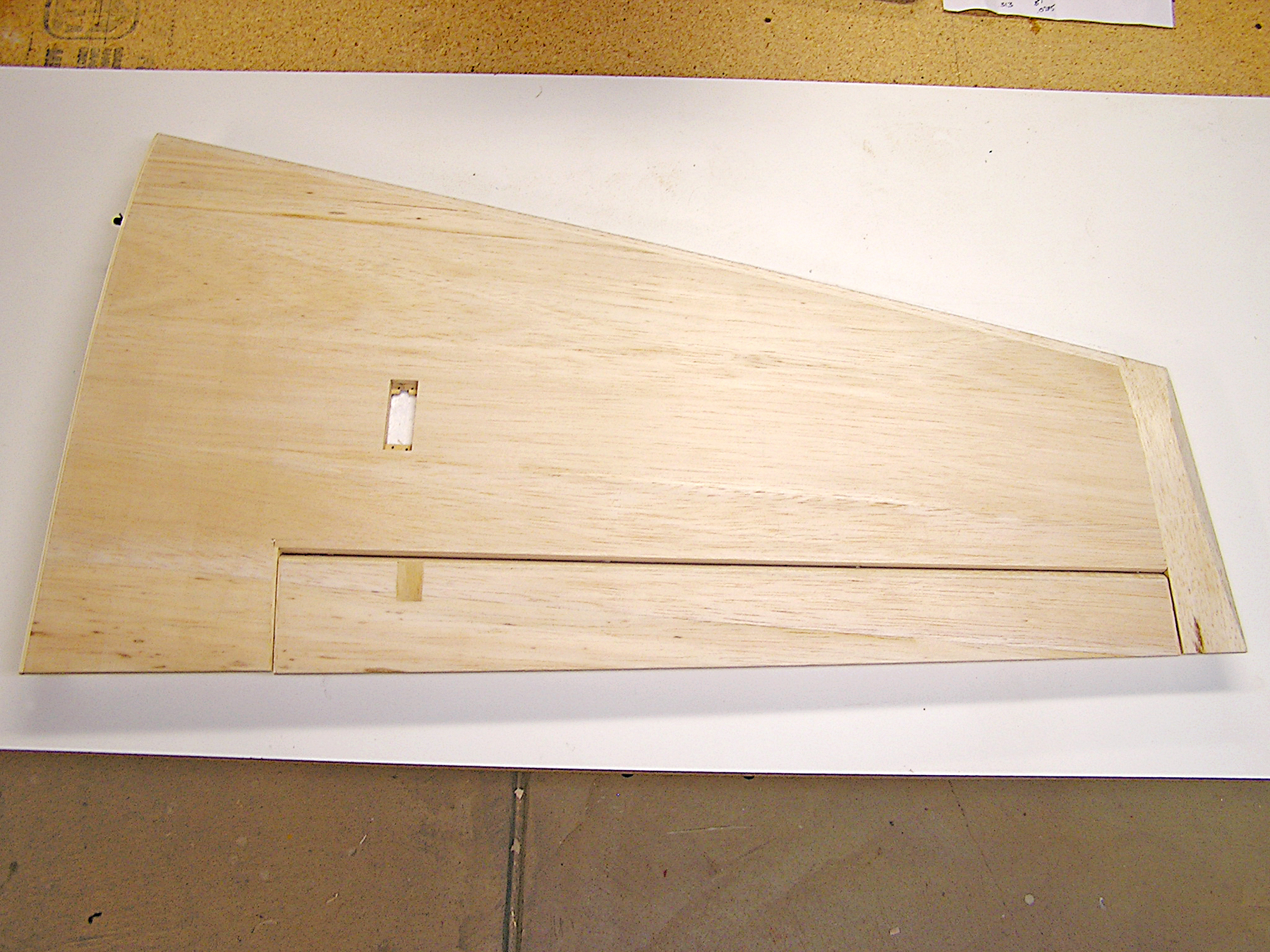
To start, identify all the places on the wing core that will eventually be cut out or cut through during the building process. This typically includes the ailerons, flaps, servo openings, landing-gear openings, etc. The wing shown will have an aileron cut out, as well as a servo opening on the bottom.
Use a permanent marker (they write best on the foam) to outline every place that will be cut. When marking the aileron cutout, keep in mind that you’re likely cutting an inner and outer boundary around the aileron so that there is room to cap the wing surface with balsa and to cap the edges of the aileron.
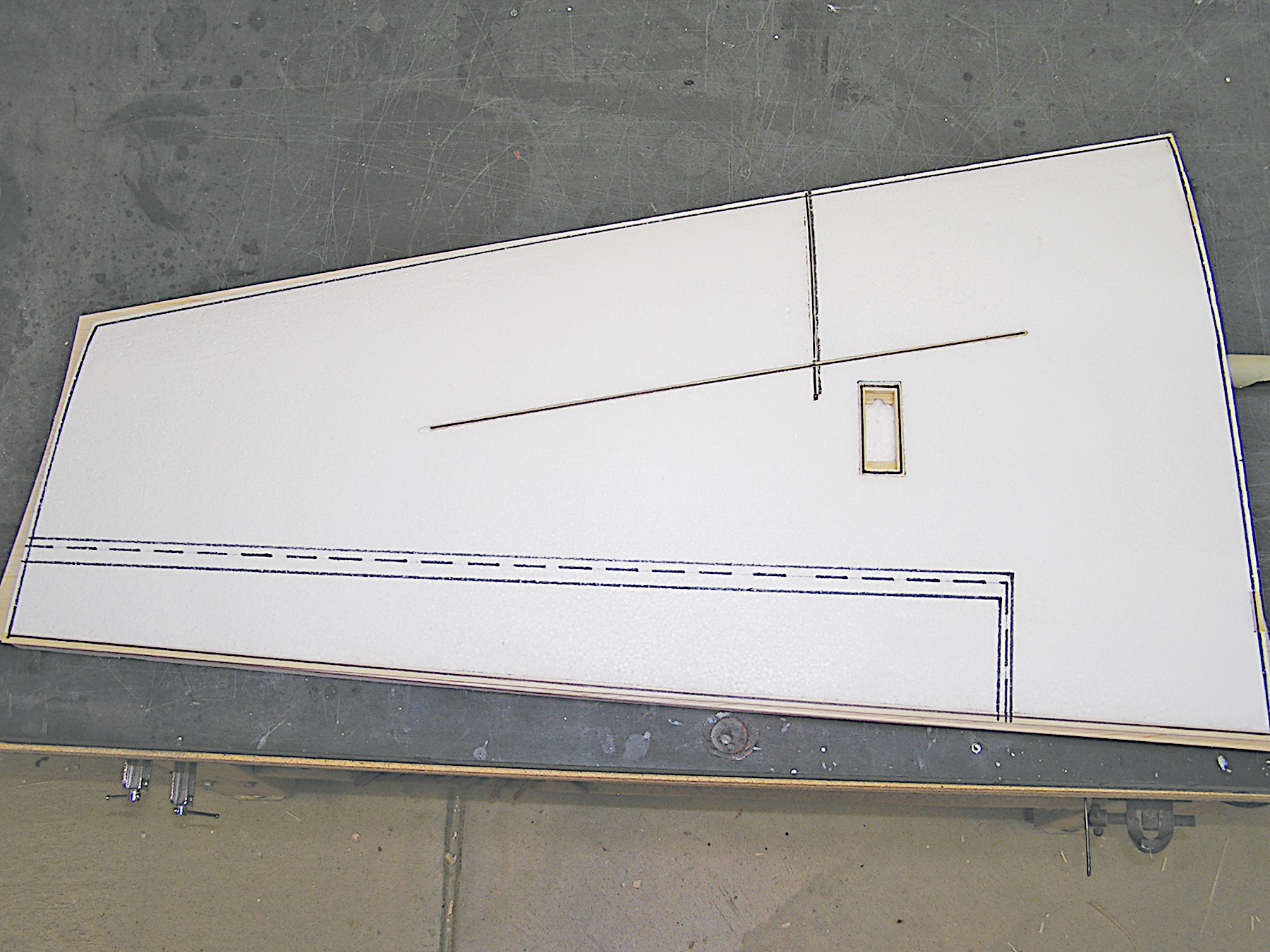
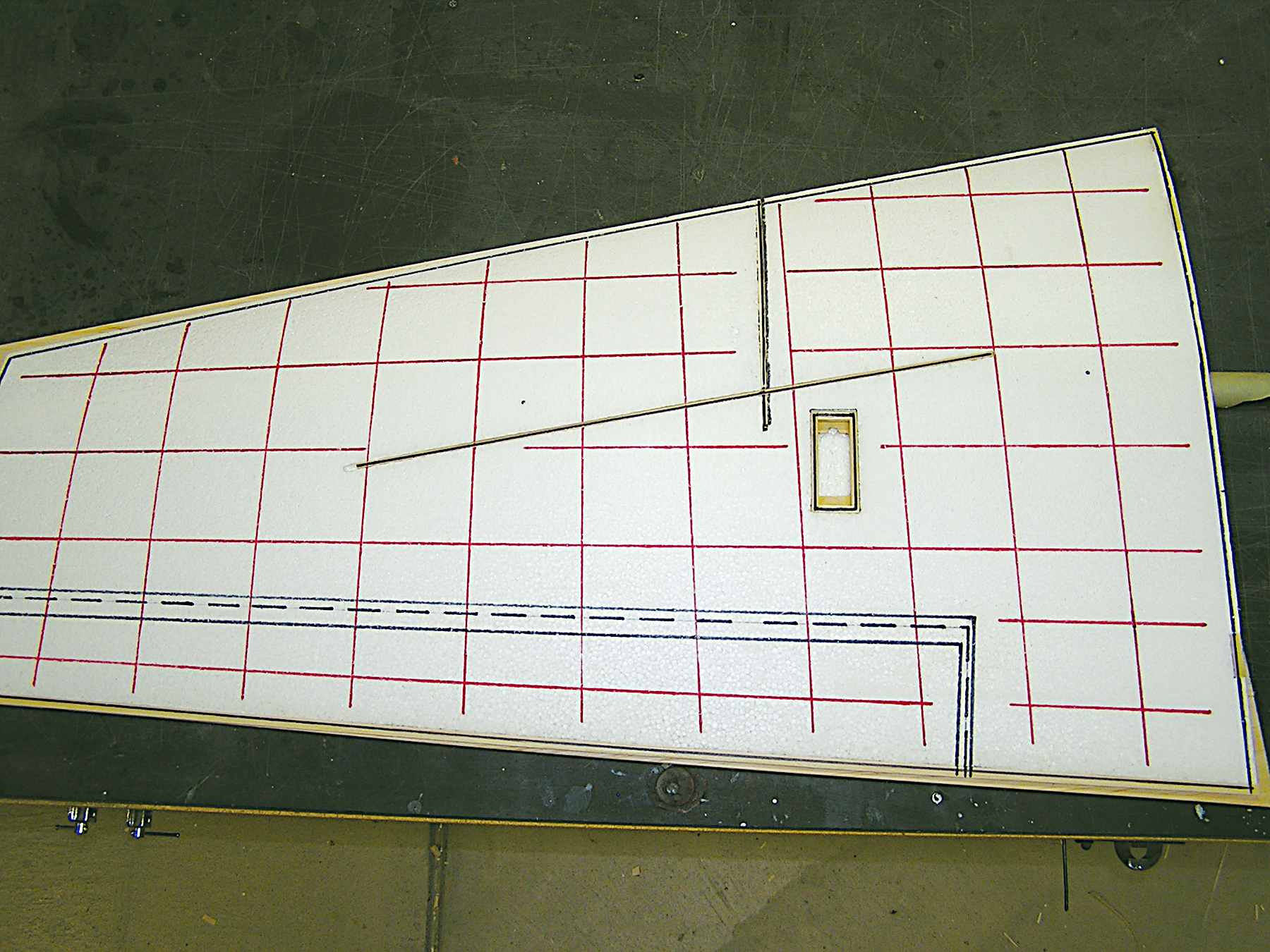
Draw accurate centerlines on the foam wing’s root and tip. Measure the center point of the wingtip (or root) at various points from the LE to the TE, and connect the points to form the centerline. Take your time; your wing will be only as straight as your centerline.
Once that is complete, test-fit the wing skins and foam cores into the foam shucks from which the wing was cut. Trim the balsa skins so that there is approximately 1/4 inch of overhang on all sides. This will make it easier to line up the wing in the shucks after the glue is applied.
Lay the entire assembly on a flat surface. I like to use a piece of old pool-table slate; it’s flat and sturdy. You can often get a nice piece for free from a local billiards repair shop. It will probably be slightly chipped and unusable for a pool table but perfect for a level building board.
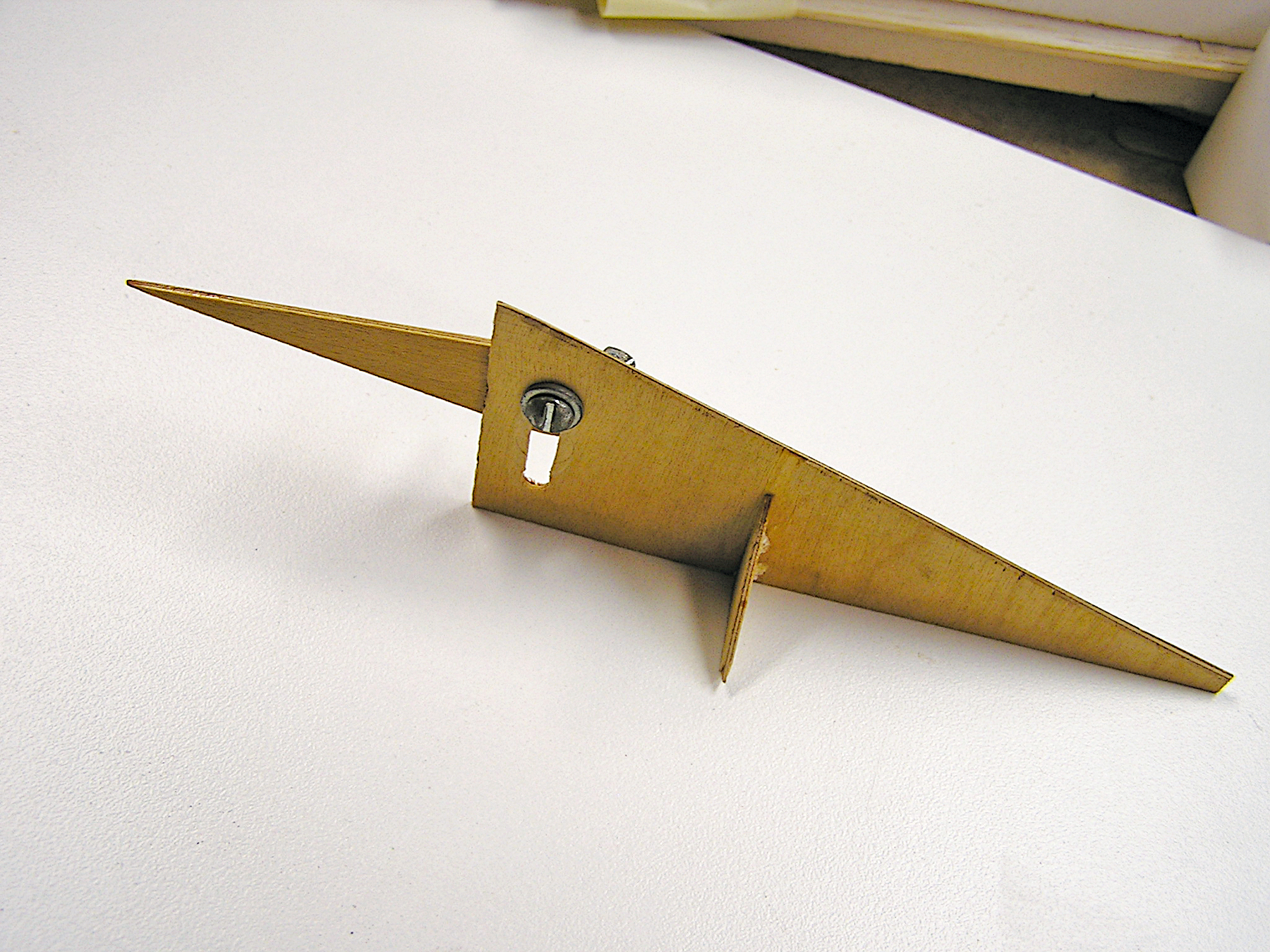
Use a height gauge (a simple homemade version is shown) to measure the distance from the tabletop to the centerline. The centerline of the wingtip should be parallel to the board, as should the centerline of the root. They will probably not be at the same height because most wings have some dihedral in them, but both centerlines must be parallel or you’ll build a twist into the wing.
Do not assume that the wing shucks are straight! Stresses that are internal to the foam often cause it to twist slightly upon cutting. Check to make sure you can get the position close. You’ll spend the time to get it perfect after you apply the glue.
Once you’re satisfied that the wing can be positioned correctly, it’s time to mix some epoxy. I use roughly 1 ounce to sheet both sides of a 2-meter Pattern model’s wing panel (approximately half of a 900-square-inch wing).
I like to use a two-hour or three-hour slow-set epoxy—preferably one that’s not too thin. This is contrary to many sheeting methods, which spread a thin epoxy across all the foam. A thin epoxy spread too thin will be quickly absorbed into the foam, and you risk getting no adherence.
If you lay a bead of thicker epoxy on the foam, you’re guaranteed to get a great bond everyplace glue is located. The trick is knowing where to put it.
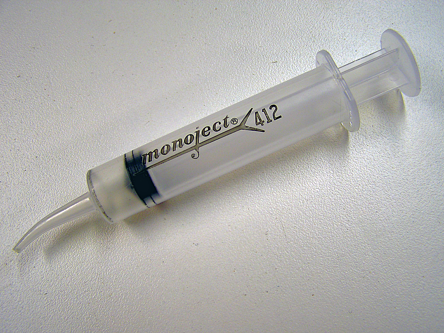
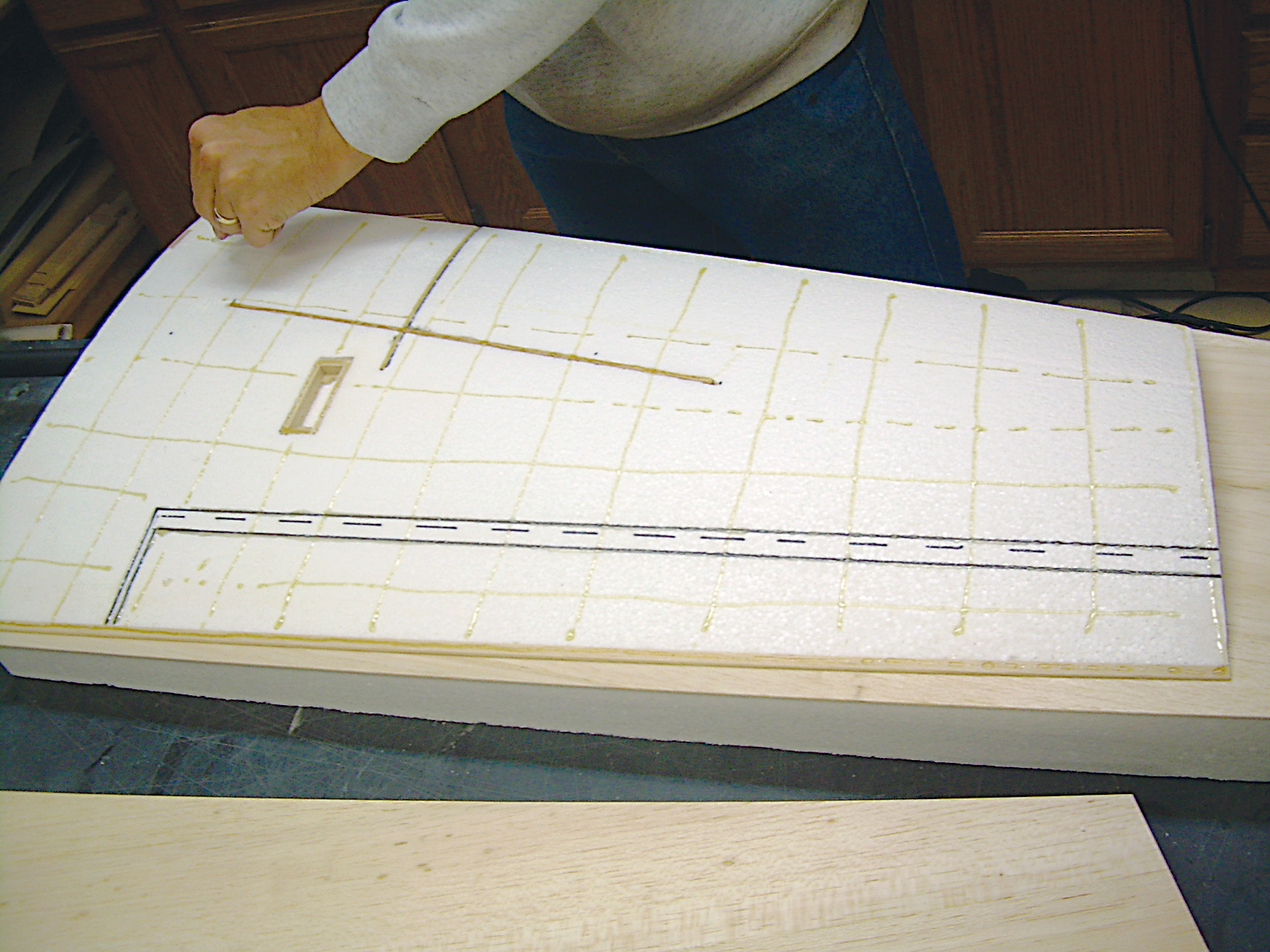
Any of the various brands of glue syringes works well to distribute a consistent bead of adhesive onto the foam. Fill the syringe with glue (it will hold roughly 1/2 ounce of epoxy) and place a small bead (approximately 1/16 inch in diameter) on all the areas marked on the foam.
When placing the glue on the perimeter, a line within 1/2 inch of the edge is sufficient. The glue will spread when the skins are placed on and weighted.
Begin making a checkerboard of glue lines, leaving just about 2-inch squares. I draw lines of glue back and forth and then up and down until there are no open areas larger than 2 x 2 inches.
Once you have distributed the glue on the foam, place the wing skin carefully over the foam, flip the wing over (I place it in the foam shuck), and repeat on the other side.
With glue on both sides and the wing carefully positioned in the shucks, place a 1/2 or 3/4 piece of plywood or particleboard over the wing to weight it down. Using the height gauge, check to make sure the centerlines on the root and tip are parallel to the building surface.
The line at the root should be the same height from the board all the way from the LE to the TE. The same goes for the centerline on the tip, although the tip height may vary from the root height. If both lines are parallel, you are sure to have a straight wing.
If the lines are not parallel, make small adjustments to move the wing in the shucks to straighten it out. Do not be afraid to have the wing slightly out of alignment with the shuck if that’s what it takes to get the measurement straight.
(Editor’s note: Those who build foam wings designed with washin should follow the plans and measure to make sure the correct incidence is maintained, as the author described where the plans were followed to ensure that the wing was built without incidence in the wingtips.)
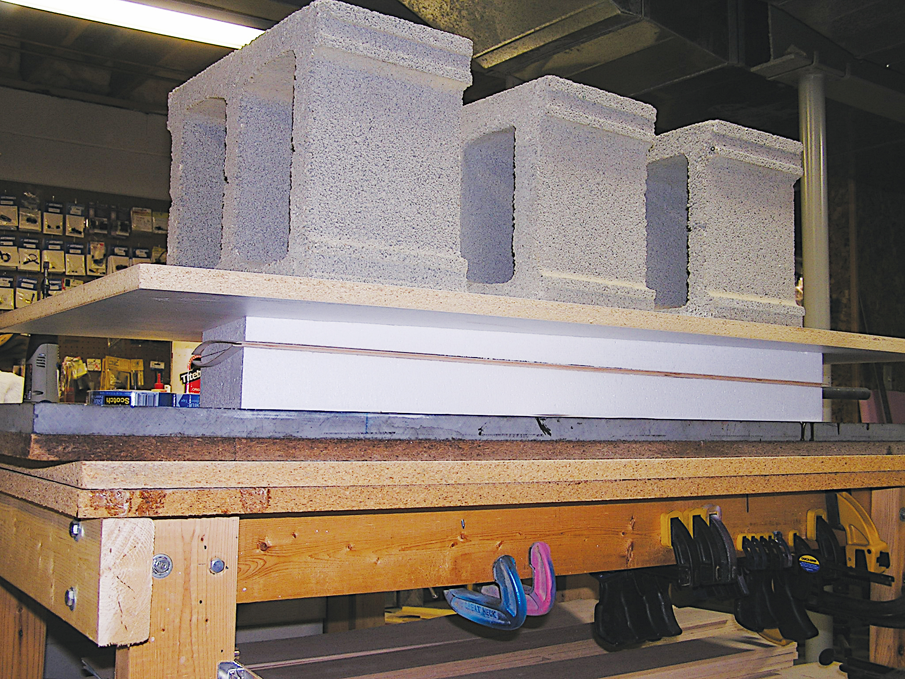
Once you have the measurements straight, add weight on top of the plywood board to apply pressure while the glue cures. Somewhere between 100 and 150 pounds is necessary to ensure a good bond. Cinder blocks weigh nearly 50 pounds each, and they are inexpensive and easy to find. Allow the glue to cure for a full 24 hours before removing the weight.
The result will be a solid, straight wing. And by using less than an ounce or so of epoxy, it will be a light one.
Materials Needed:
• Foam core and shucks.
• Balsa skins (made to fit).
• Height gauge (homemade or professional).
• Glue syringe (purchased from Sig Manufacturing).
• Two- or three-hour slow-set epoxy (adhesive—not resin).
• 1/2- to 1-inch plywood board (slightly larger than the panel being sheeted).
• Sharpie marker. (Various colors are recommended.)
• 100-plus pounds of weight (cinder blocks).
• Hard, sturdy, flat surface. (Pool-table slate is ideal.)
Cutting Wing-Tube Holes in Foam Cores
Bevel the inside of the wing-tube sleeve and harden the cutting edge with thin cyanoacrylate. Using a sharp knife, fine sandpaper, and a rasp, hone the hardened edge to a sharp point; the bevel edge should point inside.
Rotating the sharpened sleeve while gently pushing it into the foam cuts a correct-size hole. The foam will break loose roughly every 2 inches and needs to be ejected.
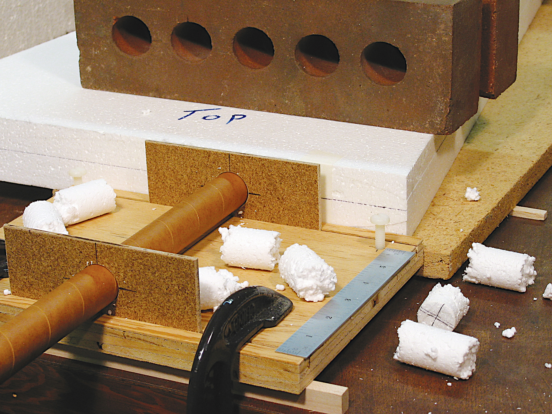
Properly aligning the wing tube in the foam cores can be challenging. The photo shows a tube guide constructed from 3/4 plywood with changeable 1/8-inch Masonite tube-guide plates to accommodate different tube sizes. The base is clamped to the workbench and has jackscrews (nylon wing bolts) at the front corners for adjusting the guide fixture to align the tube parallel to the bench top.
The wing core is supported on a baseplate, which is shimmed to locate the vertical center of the hole and set the desired dihedral. The ends of my core blanks are parallel to the aircraft centerline and butt against the edge of the guide fixture to establish the wing’s sweep angle. The hole is located slightly above center at the root so the outer end of the tube is near center.
—Jim Hiller


Comments
Add new comment