
THERE IS NOTHING better than the sound of four motors running in perfect harmony! Paul Walker sent me this great story on his new B-17. It is stunning—the engineering, the construction, and the finishing are as close to perfection as it gets! The full article is on the Flying Lines website, the link to which can be found in "Sources."
In the early 1990s, the concept of a B-17 Stunt airplane took shape. The first model was powered by four O.S. 15 FP engines with four separate tanks. A few years later, the second B-17 was built using the same four engines but with a pressure fuel system. It was complex and unreliable. It did fly, though, at the 2000 FAI F2 World Championships for Control Line (CL) Model Aircraft in Landers, France, and finished in a reasonable ninth place. It was flown a year later at the 2001 AMA Nats. It was problematic and no longer fun to fly, and that was the last flight on it for decades!
A few years ago, I got the bug to fly the B-17 again, but this time, it would be electric powered. I started by testing concepts on the first B-17. The plan was to verify that the four electric motors that I selected would be enough power. Motor mounts that would attach to the existing internal-combustion (IC) engine mounts were constructed. The size of the necessary motor was estimated, along with the ESCs and timers. Individual batteries were used in each nacelle and were not large enough for a full pattern.
The flight tests from this showed that the motors were sufficient. It flew very much like the IC version. Based on this success, the B-17 that was flown in 2000 at Landers was converted to electric. This time, the single battery, four ESCs, and the single timer were mounted in the fuselage. To complicate this installation, it was a take-apart airplane, where the wing was in two pieces and the fuselage was in three pieces. This led to many connectors in the power system, which then added weight. It flew well with one of the new Igor timers; however, it never completed a full pattern.
It was decided that the weight should be 70 ounces. The wing area was set at 700 sq. in. and the exact taper in the wing was decided by just how much the tip chord could be enlarged without looking incorrect. The fuselage side view has a scale outline, as well as the horizontal tail location, which was raised a bit so that the elevator horn would not be outside of the fuselage.
For weight reasons, various versions of the B-17 were considered. The C/D B-17 model version was enticing because it would provide a lighter empennage, which is important considering how far back it is. In the end, an F model was selected for control system clearances.
At this point, the general layout was drawn up, and an Excel spreadsheet was used to calculate weight and balance. It was clear from the start that the center of gravity was going to be the biggest issue to deal with. Motor choice was another critical issue. Any extra weight there is multiplied by four. Again, with a few calculations, a decision was made on a motor. I called Innov8tive Designs and four new BadAss 2310-1220 motors soon arrived.

It’s your money, but for the same $40, only one gives you all stainless gears, bronze reinforcements, and three MIL-STDS.
ProModeler DS180DLHV standard size servo
It was then time to finish the design work. The most difficult part of it was finding a way to install four ESCs, the wiring, and the battery into the fuselage for it to be accessible for setting the timer and ESCs. A one-piece fuselage with removable wing panels was seriously considered. That concept was eventually dropped because of the electronics installation and adjustment issues. The final solution was a nonremovable wing configuration with a removable nose section, which houses the battery. This also provides access to install and adjust the electronics.
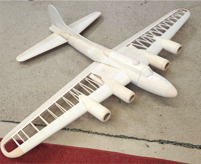
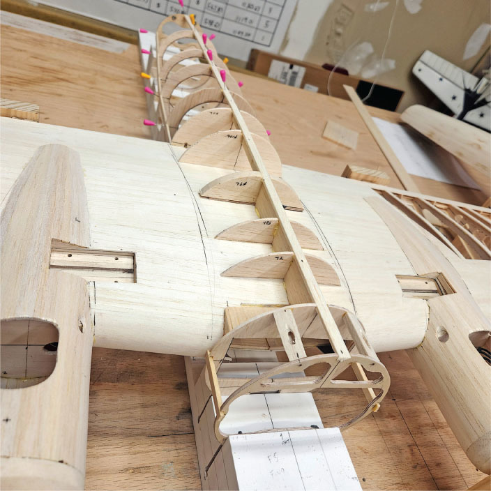
All proceeded well. The fuselage was molded with 1/16-inch sheet from a male mold. Carbon-fiber mat was attached to the inside of the shell. It was then placed back into the mold for adhesion to the carbon-fiber mat and to conform to the shape exactly. The rest of the construction was straightforward for a balsa model. An assembly jig was built to locate all of the fuselage bulkheads before the shell was added. There were no serious issues with the construction. Additional jigs were used to locate the wing, the fuselage, and the horizontal tail. It was a joyful day when the jigs were removed and the final process of preparing for painting finally started.
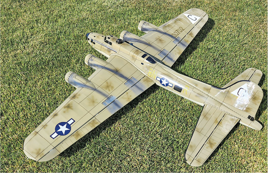
Once construction was finished, a quality finish was required, but, again, weight was extremely critical. That process went well, and the finish weight came in under the estimate. It was a standard dope finish, with many hours of sanding between every coat. There were also ink lines—a lot of ink lines. Doing ink lines around a curved, in-two-directions fuselage was not fun.
I obtained a thin, flexible straight edge and set up a vertical line on both sides of the fuselage. I then taped the straight edge to one side and applied the ink. Moving to the other side of the fuselage, the same process was then carried out. The horizontal connection on the top or bottom connected those two lines, maintaining a straight-looking line from the side. This took many weeks of time to complete. The circumferential lines on the engine nacelles were easy because they are simple cylinders. When inking was completed, the oil and exhaust stains were added, and then the clear coats went on. Just enough went on to look acceptable because the weight was already higher than what I had anticipated. It was then sanded and rubbed to a nice shine. The construction was done.
The first flight for setting up the level laps speed went well. The settings were guessed at—well, maybe better than a guess after 19 years of running electric power—which produced the 5.3 seconds per lap that I wanted. The battery capacity was also a guess, and the first flights were all 2-minute runs. After several of those runs, it appeared that the 4S battery made from Molicel 21700 4,200 mAh cells was large enough.
Finally, it was now time for a full pattern. My friend, Tim, just happened to be at my field on that day. He was totally surprised at how it flew. After all, how well should a large, four-engine airplane really fly? Well, it does fly quite well.
I look forward to the 2026 CL Aerobatics Nats in July because it is scheduled to fly there. When asked (which happens often) how it compares to the IC version, the response is that it simply doesn’t compare. By any measure, it is clearly superior. It will take a little time to adjust to it, but it will be fun!
There have been a few more flights on it and, with each additional trim adjustment, it keeps getting better. An airplane at that weight simply should not fly as well as it does.
Was the B-17 worth all of the time and effort? It absolutely was. It is fun to fly and looks great in the air. After all, how many four-engine F2B airplanes are out there competing?
SOURCES:
Precision Aerobatics Model Pilots Association (PAMPA)


Comments
Add new comment