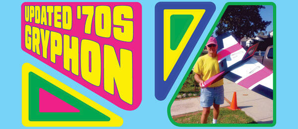
Nostalgia leads to a Slope Soaring design
By Bill O’Keefe phantom917@gmail.com Photos by the author
I became involved in RC in the early 1970s and flew Slope Soaring gliders from a bluff overlooking the Pacific Ocean. Those gliders were fairly tame, and I wanted something hotter. My wish was granted when I built my first Ron Neal-designed Gryphon.
It was a flying wing with a futuristic look to it. It could roll, loop, and fly inverted all day long. One thing I didn’t appreciate until later was its enormous wing area. It could fly in the gentlest of breezes and scoot right along over the top of the bluff.
Gryphon Redux
Fast-forward to early 2023. I wanted to fly a Gryphon again, but I couldn’t find one, or even much information about them on the internet. I gathered what scraps and pieces I could find and decided that I would build one from scratch. I had old photos of my Gryphon and used them as a general guide, but I wanted to make mine bigger. When you’re building your own design, there is a lot of spontaneous decision-making. It can be tough, but it’s also fun.
I used a 2D engineering program called Graphite for design work and spent a lot of time on my computer. When I thought I had it all worked out, I tried to produce a materials list. Even after adding about 25% "extra" material, I subsequently ended up buying much more balsa than I had estimated. Then it was time to start building!
A friend of mine had an original Gryphon, but it was in a far-too-hopeless condition to even qualify for a rebuild. I told him what I wanted to do, and he just gave it to me. One wing was crushed and only held together with MonoKote. I laid the remnant on my workbench and tried to produce some proportions to scale it up from scratch. Again, it was fun, but risky.
I placed a new hollow-core door from Home Depot on top of my workspace for a flat surface. On top of that, I used wood screws to secure two big sheets of white, B flute corrugated cardboard to draw and cut on.
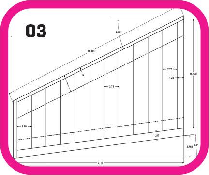
To give you an idea of how much larger I made my airplane, the original root rib of the Gryphon was nearly 12 inches long, and my new one is more than 18 inches long. There’s an issue in making something bigger. Because balsa leading edge (LE) and trailing edge (TE) stock typically comes in 36-inch lengths, the amount of sweep on the LE can determine the overall length of the wing.
The more you angle it, the shorter it becomes, so I sacrificed overall wingspan for an attractive sweep of both the LEs and TEs. Because I was designing the aircraft on my computer, I could see what proportions worked best within the limitations of what was available.
Airfoiled Again
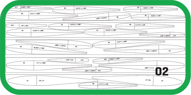
The most time-consuming aspect was coming up with an airfoil for an airplane that does not exist and that does what I want it to do. I wanted the airfoil to be symmetrical so that it would fly inverted as well as it does upright. After considerable thought, I made a symmetrical root rib (Rib 1) approximately 2 inches top-to-bottom at the Mean Aerodynamic Chord (MAC), which was at 34%. This went down to slightly less than 1 inch at the wingtip rib (Rib 12). All of the other ribs had the same proportions for the LE, TE, and MAC but were scaled down from Rib 1 as they got smaller.
It was time to start cutting out all 24 of those ribs. There was no easy way of doing it. I purchased several new #11 hobby blades and started cutting. I thought it would take forever, but I was in no rush, and it was a little easier than I thought.
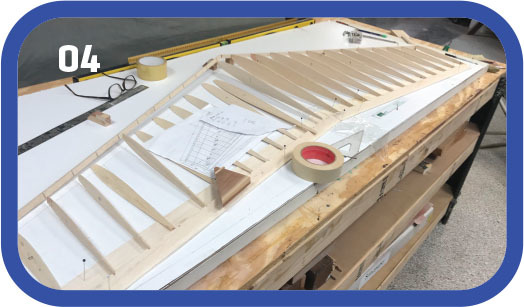
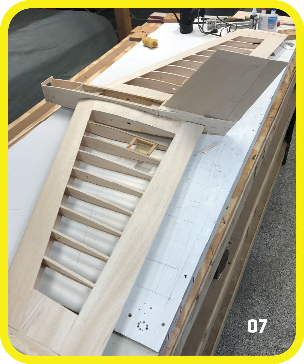
After I cut the ribs, the first thing I did was transfer my computer drawing of the wing to the white cardboard on my worktable. Magically, it started to come alive right in front of me. I started by laying out the TE and ribs. I’ve always loved the swept LEs and TEs of the airplane and I made mine 24° and 7°, respectively.
One tedious step that I had to really take my time with was cutting slots in the LEs and TEs for the ribs. I drew lines on both and (carefully) started cutting out the slots with my band saw. Not only do you have to cut them at an angle as viewed from above, but you want to make your cut the same depth from top to bottom.
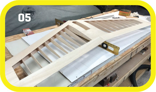
I pinned the TE to the cardboard and started to add all of the ribs following the drawing beneath it. I glued the ribs to the TE, keeping them straight. As I glued the ribs into position, the front edges of the ribs rose higher and higher from the wingtip rib to the root rib.
The ribs have a flat spot on the bottom (and top) and by pinning them down against their flat spots, this effectively gave me my washout. I was skeptical, but this worked out perfectly, and the airplane flies beautifully this way.

At a Glance
Specifications
Wingspan: 65 inches
Wing area: 1,100 sq. in.
Length: 38 inches
Height: 10.5 inches
Weight: 33 ounces ready to fly.
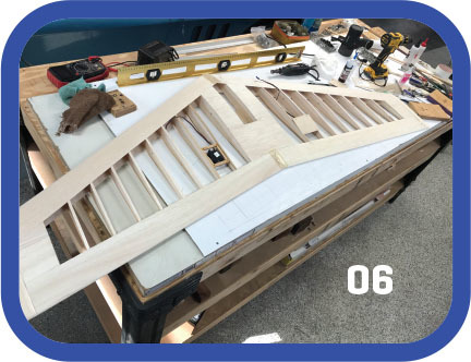
My next task was to carefully glue the LE to the relatively fragile ribs. Again, this takes time to do correctly. Constant checking was a must because the sheeting came next to increase the strength of the wing. I have a gram scale and weighed every piece of balsa sheeting to keep the weight evenly distributed.
I sheeted the top side of the TEs then flipped the wing over and did the same on the bottom. I followed the same procedure for the LE sheeting. I next added the sheeting for the center section and wingtip area then put capstrips over each rib for strength and a uniform plane for covering. Fiberglassing the center sections, top and bottom, made it extraordinarily strong. It was starting to look good!
Upsized Fuselage
I had a printer that could print out full-size templates for the ribs and fuselage; however, putting the root rib with all of its extra goodies in the right location and incidence on the fuselage sides was trying. I ended up trimming a lot of the wing cutout into the fuselage sides. When I got one side done, I transferred that cutout to the other side. As much as I had hoped it would be the same, it wasn’t. In other words, the right wing outline wasn’t exactly like the left wing. I eventually made it acceptable and moved on. I kept checking the balance of the aircraft and found areas that needed to be addressed.
Along with making the wing bigger, I wanted to lengthen the nose from the original design. This worked out well because I could put my battery way up front with that long nose. I made a hollowed-out nose block and put the battery in there. After I made an access hatch and holes for the elevon servo wires, the fuselage was essentially complete.
The servo supports were next and proved a bit tedious. The wing wasn’t very thick back there because I wanted the shortest length for my pushrods. I made several trial support platforms before I found a set that worked. Working out servo linkages has always been fun for me.
I enjoyed designing the tail fin. It just looked kind of sexy from the side. I made it detachable with strong internal supports. The time I’ve spent building RC Pattern models paid off and the fin came out true. I also included a decal of my favorite beverage on the tail.
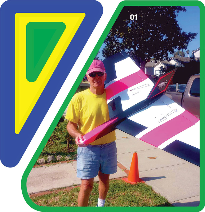
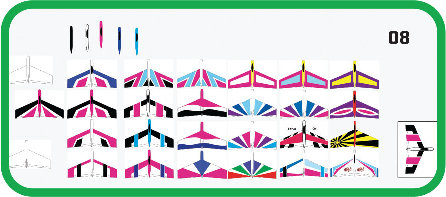
One of the things I really love about building model aircraft is coming up with a good color scheme. Once again, my RC Pattern background proved helpful. There are certain colors that can be seen better than others in nearly any lighting situation. One of those colors is pink. I’ve always had that color on my airplanes. When doing a rolling or looping maneuver, I can always tell the orientation of the aircraft.
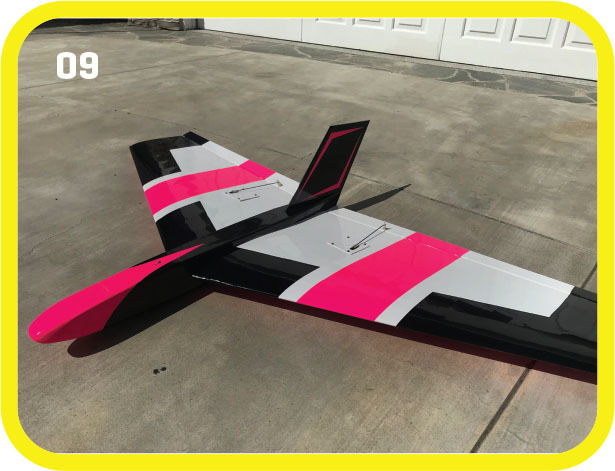
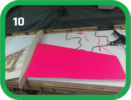
I laid out several color schemes in Adobe Illustrator and finally settled on one. Unfortunately, Top Flite MonoKote stopped making pink. I searched everywhere with poor results. I wound up with a color that I’m happy with: Hangar 9 UltraCote Fluorescent Neon Pink. The entire bottom was covered in this pink, while I covered the upper wing in black, white, and pink.
My completed Gryphon has a wingspan of 65 inches, with 1,100 sq. in. of wing area. It is 38 inches long and 10.5 inches tall. The ready-to-fly weight is only 33 ounces.
Maiden Flight
When my upsized Gryphon was ready to fly, I had an appointment, so I let a friend do the test flight. He recorded it and it shows the flying characteristics. The area is known as Parker Mountain, in Southern California, and can have extremely strong wind, but on this day, it was light and playful. Having never before designed an aircraft, I was quite happy with the results. Refer to the "Sources" section for a link to the video.
Building and designing an aircraft from scratch probably isn’t for everyone. It takes patience, time, and perseverance. There were many times that I asked myself, "What am I doing?" It is incredibly rewarding, and I knew I wanted an airplane like that Gryphon I flew in the ‘70s. As George Herbert said long ago, "Where there’s a will, there’s a way."
SOURCES:
Adobe Illustrator
Gryphon Maiden Flight Video
Hangar 9
Home Depot


Comments
Add new comment