Twin Vapor
By Tim Bailiff casurfish@aol.com Photos courtesy of Maggie Madril
As seen in the August 2025 issue of Model Aviation.
Materials List
I have included many construction photos in this article, and I suggest that you refer to them. Please note that either the Vapor or Night Vapor would work fine. The same goes for the following listed Night Vapor parts as well. Also, either a Blade mCX or mCX2 (five-in-one) helicopter controller will work great.
- One new or used Vapor or Night Vapor
- One used mCX controller or a new E-Flite EFLH2401 unit
- One E-flite 150 mAh 3.7-volt LiPo battery
- One Night Vapor motor
- One Night Vapor gearbox
- One Night Vapor propeller with spinner
- One 6-inch piece of .050-inch carbon-fiber rod
- One 12-inch piece of .030-inch carbon-fiber rod
- One piece of 3 × 4 × 1/16-inch balsa sheet
- One spool of upholstery thread
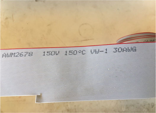
- One 26-inch 30 AWG multiconductor ribbon cable
- Two .05-inch male nano connectors
- One 2-inch piece of 1/32 heat-shrink tubing
For those of us who love Vapors, there can’t be enough written about them. In 2023, I submitted two Vapor Bash articles that chronicled various modifications made to our beloved Vapors. They were so well received that I soon had numerous emails asking specific construction questions. That gave me the notion of revisiting each of these fun, little airplanes individually and in detail. Let’s start with the Twin Vapor.
A Smoked Controller
I found this to be a particularly fun and interesting project. Its conception began when I was offered a Night Vapor that had experienced an accident involving a reversed battery and a smoked controller.
My friend explained that after seeing that little puff of white smoke, he knew it was bad news and simply didn’t want to mess with it. That little Night Vapor provided me with an opportunity to pursue an idea that I had toyed with years ago. At the time, technology was different and, although I had some success, it was limited.
My idea was to replace the Night Vapor’s fried controller with one harvested from an older Blade mCX helicopter. The mCX and mCX2 were designed with a coaxial, counterrotating rotor head system. It’s a clever design using two separate motors, each driving one of two main rotors. There is no tail rotor, so for yaw, the controller simply speeds up or slows down one or both main rotors. It allows torque to do the job.
Something Special
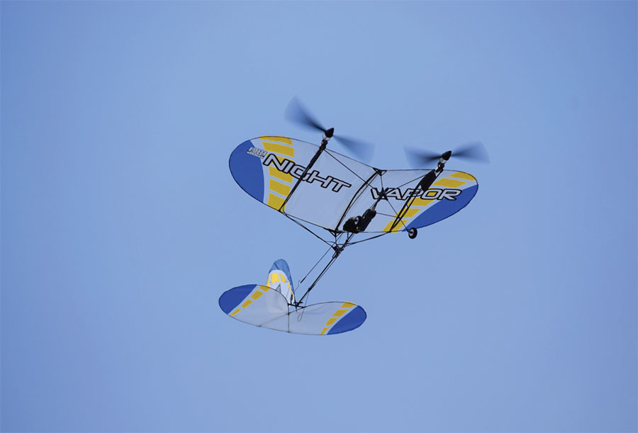
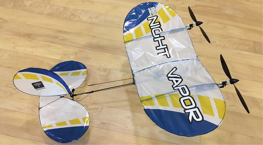
My goal was to build a twin-motor slow flyer with motors that could be controlled simultaneously and independently. I knew the mCX controller was what I needed. I felt that by replacing the single motor assembly with twin, wing-mounted motor assemblies, the Night Vapor could be transformed into something special, and I was right! It worked perfectly and made the new Twin Vapor a real pleasure to fly. Not only can it turn using its rudder, it can also effectively turn using differential thrust. So, are you ready to build one?
I use a Spektrum DX7 transmitter. The mCX control unit works perfectly with it. Any DSM2 or DSMX transmitter will work as well. Should you be fortunate enough to have a second motor/gearbox/propeller assembly harvested from a Vapor, you can check off items four through six on the list of materials. Other than glue and a few incidental items, that’s it! Time to start building.
Remove the Old Controller
Start by removing the old controller/receiver that comes attached to the Vapor. That requires unplugging the motor and the lights (assuming you are working with a Night Vapor). Gently peel off the (black) rubbery glue and bend back the clips that hold the controller in place. It should now lift off.
Carefully remove the rudder and elevator pushrods that connect to the servo arms on the controller. Once freed, the pushrods will stay attached to the airframe held by their guides. I suggest using a little painter’s tape to keep things from flopping around. If the old controller is good, keep it for a future project.
If you have a Night Vapor, the mCX controller won’t support the lights. Now is a good time to carefully remove the LED lights and associated wiring. Work slowly and gently so as to not rip the covering or damage the airframe. Also remember to remove the wire junction point located at the rear of the center rib beneath the wing.
Move the Wing Forward
When the lights and wires are gone, you should slide the wing forward 3/4 inch and glue it into place with CA. Moving the wing will help compensate for the additional weight that the second motor assembly brings to the front of the airplane. My wing slid easily, but yours might be glued in place. To free the wing mounts, work your hobby knife between the glue and the fuselage. Take your time and work carefully because you want to preserve their integrity.
Modify the Controller
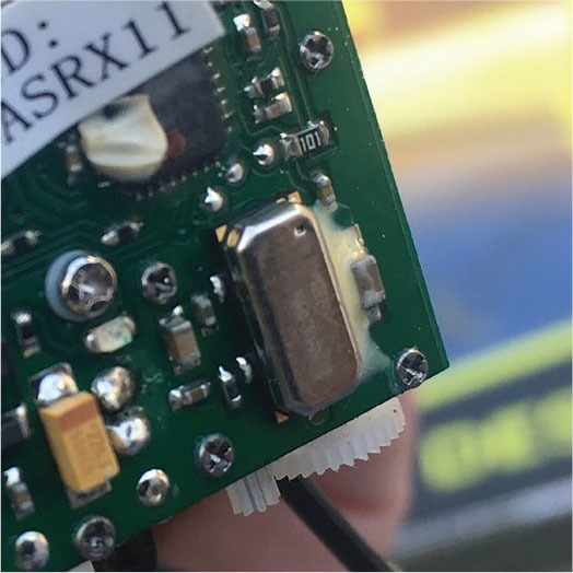
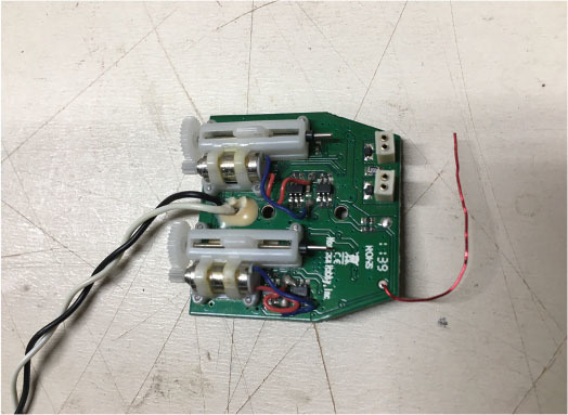
Before installing the mCX controller, modify it slightly by disabling its gyro. The controller is designed to mount vertically in the mCX and uses the built-in gyro to help stabilize the helicopter along its yaw axis. When mounted horizontally, the gyro interferes with the Vapor along its roll axis. Experience has shown me that it can escalate into a catastrophic event.
The gyro is located on the controller circuit board, directly under a small rectangular, metallic cover. Check out the construction photos to help identify it. Note: On some older mCX controllers, the cover is mounted on the side opposite the servos. On newer ones, it’s mounted on the same side as the servos.
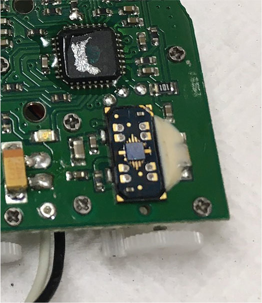
Pick off the glue, if any, and gently pry off the metal cover. Beneath it you will find a delicate-looking micro mechanism. Everything that doesn’t lay flat should be carefully pulled off. One easy tug with tweezers or small pliers usually removes the entire works. Remove only the contents beneath the cover, not the entire component. Again, use the construction photos for clarity.
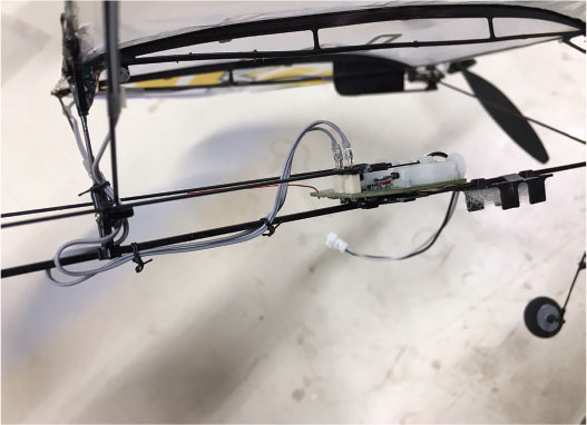
Install the New Controller
Begin by binding your new controller to your transmitter. Check that your servos move in the appropriate direction and are centered. Using the servo gears as your forward reference, the right servo should move forward with right aileron (actually, rudder) input and the left servo should move forward with up-elevator input. Use your transmitter settings to make the appropriate changes then power down.
Next, carefully cut off any protrusions or glue remaining on the plastic mount. The controller should lay flat, with the servos facing up and their gears facing forward. With the servo arms centered, reconnect the pushrods accordingly.
Before gluing, slide the controller forward or back slightly to center both the rudder and elevator. You might need to reposition the plastic mount itself to align with the controller. When you are satisfied with the alignments, use hot glue to secure the controller flat onto the mount. As the glue cools, be sure that the control surfaces remain in a neutral position.
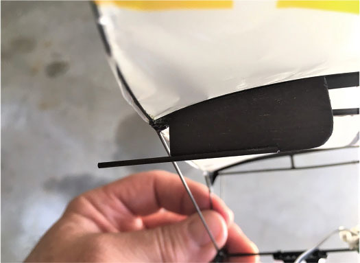
Add Struts
The Vapor wing is inherently lightweight and flexible. Because it will soon carry two motor assemblies, struts must be added for support. You’ll use .030 carbon-fiber rods to make four struts that will connect to the ribs and plastic wing post supports near the fuselage.
The wing ribs (one on each side) aren’t always spaced the same distance from the center rib, so measure and cut each strut separately. Using medium CA, lightly tack-glue the two forward struts to the front of each rib, and then onto the back side of the plastic base holding the forward wing post. Similarly, the two rear struts should be tacked to the rear of each rib, and then lightly tacked to the plastic base of the rear wing post. You will need to place your struts over and/or under the pushrods as necessary. Use the photos for clarity.
Check to be sure that you didn’t accidentally build a twist into your wing. When you are satisfied, place a wrap or two of upholstery thread around each junction point. Finally, add a small drop of CA to each wrap and your struts are done!
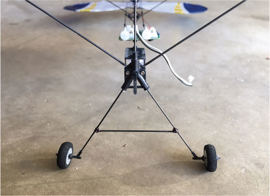
Support the Landing Gear
The landing gear will also need support because of the additional weight of the second motor assembly. A single 2-inch crossbar placed between the landing gear struts 1-1/2 inches down from the fuselage will accomplish this. You will again use .030 carbon-fiber rod. When you’re satisfied with the wheel alignment, place a wrap or two of upholstery thread at each junction point and secure it with a small drop of CA glue.
Remove the Motor Removing the motor should be carefully done with the help of a fresh X-Acto-type hobby knife. Remove the entire propeller/gear box/motor assembly in one complete piece. The mount holding the motor is thin, so use all precautions not to crack it!
I chose to shave the bottom off of the plastic mount by carefully sliding my hobby knife forward along the fuselage. I used the point of the knife to help release it from the sides of the fuselage. Cut only the glue and not the plastic mount itself.
If you purchased separate components for your second motor assembly, put them together now. If you are harvesting a motor from another Vapor, follow the same procedure, remembering to preserve the plastic mount as much as possible.
Consider placing a cap of sorts onto the bare front end of your fuselage. I glued a tapered plastic wheel keeper onto mine. This step isn’t critical, but it does give it a nice, finished appearance.
Twin Motor Mounts
Build the two motor mounts using 1/16-inch balsa sheet and .050 carbon-fiber rods. Begin by cutting two balsa pieces 1-1/2 inches long and 3/4 inch wide, with the grain running lengthwise. Using the photos as reference, cut off the top of each piece of balsa to match the top forward curve of the ribs. Cut a little at a time and you’ll have no problem. You should also round off the bottom rear corner to give the mount a finished appearance.
Avoid the strut attachment by positioning the mounts 1/4 inch back from the leading edge (LE) of the wing on the outside of the ribs. It’s important that the bottom of each mount remain parallel with the bottom of the ribs.
Cut two 1-3/4-inch lengths of .050 carbon-fiber rods. Remove a 1/16 × 1-inch piece from the forward bottom side of each balsa mount, forming a recess. Use medium CA to glue the carbon-fiber rods into these recessed areas, leaving 3/4 inch of carbon-fiber rod protruding forward.
If you plan to color your mounts, it’s easiest to do it now. I used black Magic Marker. It weighs nothing and covers balsa and glue well. Use a little sandpaper to lightly roughen the outboard side of both ribs where the balsa mounts will attach and use 5-minute epoxy to attach the mounts to the ribs 1/4 inch back from the LE. Don’t be concerned if the mounts tilt when they are pressed firmly against the sides of the ribs. Your motor assemblies don’t care and will be tilted upright when they are glued into place.
Motor Leads
Before the twin motor assemblies can be mounted, you will need to lengthen the motor leads. I used two 13-inch lengths of 30 AWG wire taken from multiconductor flat ribbon cable. Each length has two conductors. (I acquired my cable from a local electronics store’s scrap bin, where I also found 1/32-inch heat-shrink material. Both are readily available online.)
Cut each existing motor lead off, leaving 3/4 inch. Prepare the ends of the leads for soldering by stripping off 1/8 inch of insulation. Do the same to the ribbon cable after splitting the insulated conductors roughly an inch. Slide 1/4-inch pieces of 1/32-inch heat-shrink tubing onto the ribbon wires before soldering. After the soldering is done, insulate the joints by sliding the heat-shrink tubing over the joints and shrinking it.
Prepare the other ends of the two extended motor lead wires, again using heat-shrink tubing to insulate the solder joints. This time, you will solder each pair of wires to a .05 male nano connector. The two nano connectors will then easily plug into your mCX controller.
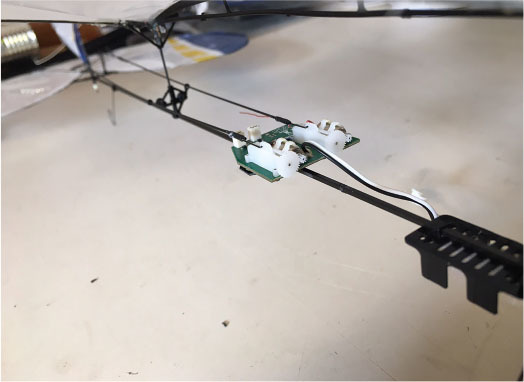
Attach the Motor Assemblies
Use 5-minute epoxy to glue both motor assemblies onto their new motor mounts. They should be pushed on just until the motors almost touch the wing’s LE. As the glue dries, make sure that the motor assemblies remain upright and aligned.
Route the motor leads back along the ribs then down the rear struts to the fuselage. Use 1/2 × 1/4-inch pieces of Blenderm tape to secure them every few inches. Plug the connectors into jacks at the rear of the control unit.
Before you tie the leads in place or secure any slack wire, turn on your transmitter and plug in your flight battery. Now try your throttle. Both motors should spin in the same clockwise direction. If there is a problem with rotation, simply unplug that connector and turn it around and place it back into the same jack.
After both motors rotate properly, with the throttle partly advanced, move your rudder stick left. The right motor should rev up and the left motor should slow down. Obviously, the opposite should happen when the stick is moved to the right. If there is a problem, simply swap the position of the connectors then secure any loose or slack wire. I used upholstery thread.
Don’t be concerned that the propellers turn in the same direction. The plastic motor mounts have just a bit of right thrust built in and that takes care of most torque issues. Any final adjustments can be made in the air.
Hey, it’s time to go fly!
Double the Fun
What fun you are about to have with your new Twin Vapor. I’m sure you are anxious to fly, so let’s get airborne.
Takeoffs are accomplished by gently and smoothly applying throttle. As the airplane accelerates, keep it straight by using your left (rudder) stick. Almost immediately, you are up. Full throttle isn’t necessary. It actually limits the thrust-vectoring capabilities, so take it easy.
When you’re at a comfortable height, throttle back and trim for straight-and-level flight. Try a few rudder turns and thrust-vectoring turns. It handles both well. Power management is the key to a nice, gentle flight. Too much power or speed can make your airplane act slightly unruly.
Find that sweet spot and you will be convinced that the Twin Vapor is a pleasure to fly. After all, it is still a Vapor, and what Vapors do best is gracefully cruise around. Landings are easy and predictable.
Use a little throttle to carry you in and slowly fly it down to the ground. When it is a few inches off the runway, cut the power, flair gently, and that’s it. You are down and can taxi back to your hangar.
Pilot’s Lounge
Congratulations on a successful maiden flight. The Twin Vapor is a pleasure to fly, isn’t it? As you know, this little slow flyer was originally designed to fly indoors and that’s still what it does best; however, that doesn’t mean it can’t fly outside. If you wake up to a calm morning, the Twin Vapor makes a perfect front yard flyer.
I hope you have as much fun flying your new airplane as I have had with mine. Twins are more fun to fly! I wish you smooth air and blue skies. Stay safe and stay well. Fun stuff.
SOURCES:
Horizon Hobby/E-flite
Spektrum RC
Blade


Comments
Add new comment